


TRACKER 5380 Installation and Operation Manual
52
NAVMAN
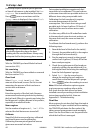
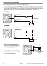
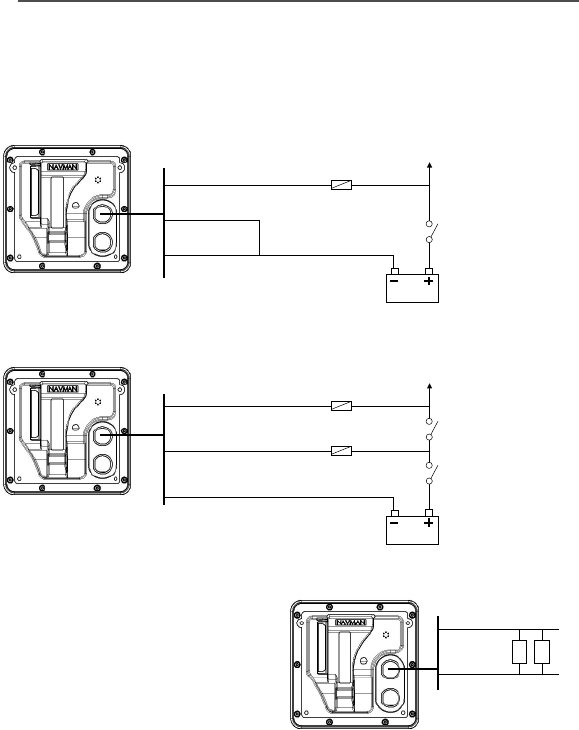
Power/data cable
Red
Yellow
Black
External beepers or
lights
Main switch
12 V DC]
Fuse 2A
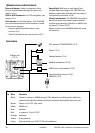
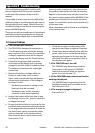
The power/data cable has a black locking collar and flying leads.
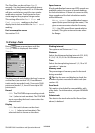
1 Wire the TRACKER for auto power to have the TRACKER turn on with the boat’s ignition switch
or to to record engine hours or if the TRACKER must add up the total fuel used (for example if
Navman petrol/gasoline fuel sensors are installed or if SmartCraft is installed without fuel tank
level sensors). Otherwise wire for basic power (for more information, see section 2-2).
Basic power
Auto power
During setup, set up Auto power off (see sections 2-3 and 17-1)
Power/data cable
Yellow
Red
Black
Ignition
Ignition switch
Main switch
12 V DC]
Fuses 2A
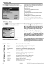
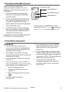
Power/data cable
Red
Green
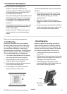
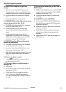
2 Wire any external alarm beepers or
lights. The alarm output switches to
ground to sound the alarm. If the current
is more than 200 mA, fit a relay.
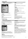
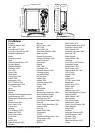
3 Connect the power/data cable to the
black display unit connector; turn the
collar to lock the connector.
Black
Black
Black
15-4 Installation: Power/Data cable