


Appendix A Register-Level Programming
© National Instruments Corporation A-3 NI-IMAQ for IEEE 1394 Cameras User Manual
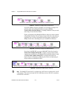
• Read Quadlet Block—Reads an array of quadlets from a specified
memory location and range
• Write Quadlet Block—Writes an array of quadlets to a specified
memory location
Note In LabVIEW, only the quadlet block variants are exposed.
Usage
To perform a register-level access, specify a memory location (or offset)
and data storage. IEEE 1394 memory locations are specified as 48-bit
values. The upper 20 bits are filled in by the driver. The low-level register
primitives accept the lower 28-bit offset. The memory storage contains the
result/desired data when transferring.
Basic Example
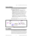
The isonchronous enable register indicates active video transmission. To
read the ISO_EN register (0x614), calculate the memory offset by adding
the specified offset to the base register. The base register is 0xF0F00000 for
most IEEE 1394 cameras.
0xF0F00000 + 0x614 = 0xF0F00614
The value is read, and the result is placed in the specified memory location.
read quadlet (0xF0F00614) = <iso_en>
where <iso_en> = (0x80000000 or 0x00000000).
If bit 0 has a value of 0x80000000, the bit is on, and the camera is
transmitting video data. If bit 0 has a value of 0x00000000, the camera is
not currently transmitting data.
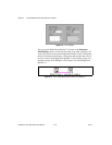
Advanced Example
The advanced feature described in this example is specific to Basler
IEEE 1394 cameras. The advanced feature replaces the live video feed with
a static test pattern.
According to the user documentation for the Basler A601f camera, the
TEST_IMAGE register is located at advanced offset 0x0098. You can
enable a static test pattern by setting bit 17 of the TEST_IMAGE register.
To get the advanced base register, first read ADVANCED_FEATURE_INQ