


HTXD6i RIDE-ON TROWEL • OPERATION MANUAL —REV. #0 (03/23/12) — PAGE 19
COMPONENTS
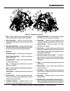
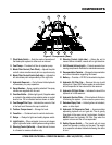
17. Pitch Mode Switch — Sets the mode of operation of
the blade pitch system to either auto or manual.
18. Fuel Pump— Provides fuel flow to injection pump.
19. Blade Pitch Control (Twin Pitch) — Adjusts the pitch
on both rotors simultaneously but non-synchronously.
20. Blade Pitch Control Switch (left side) — Adjusts the
left side blade pitch independently of the right side.
21. Hydraulic Reservoir — Part of frame. Holds hydraulic
oil necessary for pump operation.
22. Spray Nozzles — Spray nozzle for retardant. Two spray
nozzles are supplied with this unit.
23. Overflow Bottle — (Behind grill guard.) Supplies water
or coolant to the radiator when radiator water or coolant
level is low. Fill to indicated level as shown on bottle.
24. Fuel Gauge/Filler Cap — Indicates the amount of fuel
in the fuel tank. Remove this cap to add fuel.
25. Toolbox Compartment — Storage for tools.
26. Fuse Box — Contains fuses for control electronics.
27. Relays — Relays for lights and safety bypass switch.
28. Light Switch — When activated, turns on six halogen
lights. Lights offer better visibility when working indoors
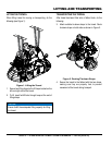
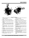
29. Steering Control (left side) — Allows the unit to move
in a forward or reverse direction only.
30. Steering Control (right side) — Allows the unit to
move in either a forward, reverse left or right direction.
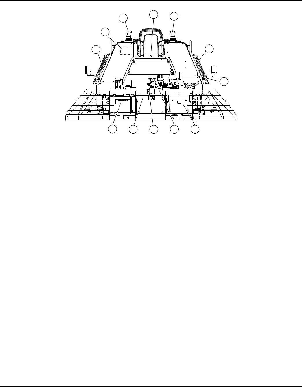
31. Grill Guards (left and right) — Protects operator from
moving components. Remove for maintenance access.
32. Documentation Canister — Storage for documentation
and other information regarding the trowel.
33. Battery — Provides +12V DC to the electrical system.
34. Hydraulic Oil Filler Cap — Remove this cap to add
hydraulic oil. Open ONLY when system is cooled down
and all expanded oil has returned to the reservoir.
35. Hydraulic Oil Sight Glass — Indicates the level of the
hydraulic oil in the reservoir.
36. Hydraulic Suction Filter — Filters hydraulic fluid prior
to entering the system. (10 Micron absolute synthetic media.)
37. Retardant Spray Tank — Holds 5 gallons of retardant,
water, or other liquid.
38. Hydraulic Oil Expansion Tank — Accommodates
expanding hydraulic oil as it gets hot. The oil gravity
flows back to the reservoir as it cools down, therefore
NEVER open the Hydraulic Oil Filler Cap when the
system is warm and the oil has expanded.
39. Safety Bypass Switch — The trowel will not move
unless an operator is sitting on the seat. The weight
of an operator activates the switch allowing the rotors
to turn.
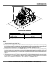
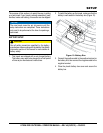
Figure 5. Components (Rear)
31
38
29
30
39
31
32
36 3334
37
35