


PAGE 18 — HTXD6i RIDE-ON TROWEL• OPERATION MANUAL — REV. #0 (03/23/12)
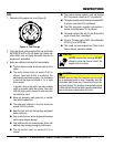
COMPONENTS
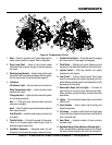
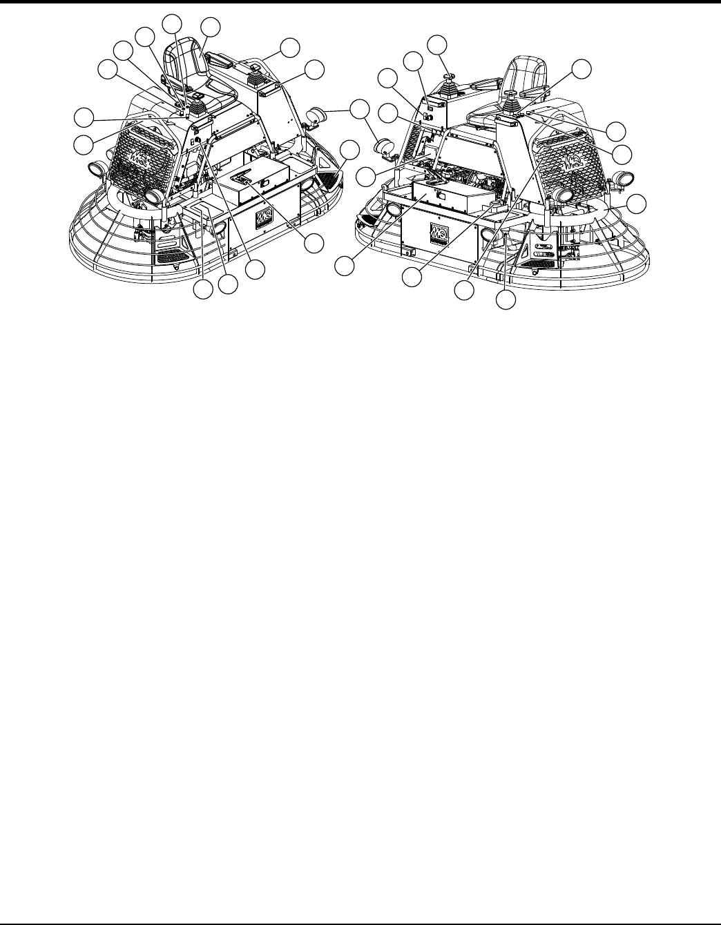
1. Seat — Place for operator to sit. Trowel blades will not
rotate unless operator is seated. Seat is adjustable.
2. Stop Lamp (Red) — Used to relay trouble codes
information that is severe enough to warrant stopping
the trowel.
3. Warning Lamp (Amber) — Used to relay trouble code
information that is reporting a problem with the system
but the trowel need not be immediately stopped.
4. Indicators:
Oil Indicator Light — Not connected on this machine.
Water Temperature Light — Lights red when water
temperature is high.
Charge Indicator — Lights red when electrical system
is not charging properly.
Aux 1 — Cold start lamp, indicates when cold start
sequence is enabled.
Aux 2 — Filter Condition lamp Indicates when hydraulic
filter needs serviced
Cold StartAid — Indicates when engine cold start aid
is enabled.
5. Throttle Switch — Controls the speed of the engine.
Press up to increase engine speed (high). down to
decrease engine speed (low).
6. Fuel/Water Separator — Separates water, dirt and
sludge from fuel preventing engine component wear.
7. Cruise Control Switch — Press this switch to engage
the cruise control. Press again to disengage.
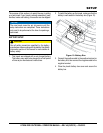
8. Pitch Block — (Behind grill guard) Measure at the
service port and adjust pitch pressure at the pitch block.
9. Ignition Switch — With key inserted, turn switch
clockwise to start engine.
10. Foot Pedal — Controls blade speed. Slow blade
speed is accomplished by slightly depressing the foot
pedal. Maximum blade speed is accomplished by fully
depressing the foot pedal.
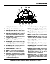
11. Removable Steps (left and right) — Provides for
safe footing for mounting and dismounting trowel.
When removed, provides access to spider and blade
assemblies.
12. Lights — Six low voltage halogen lights are provided
with this unit.
13. Grab Handles — Use to assist safe mounting and
dismounting trowel.
14. Lift Loops — Located on both the left and right sides
of the main frame. Used when the trowel must be lifted
onto a concrete slab.
15. Hour Meter — Indicates number of hours machine
has been used.
16. Retardant Spray Control Buttons (left and right) —
When pressed allows retardant spray to flow through
the spray nozzle located at the front of the machine.
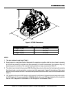
Figure 4. Components (Front)
1
13
14
21
11
12
10
28
27
15
16
7
6
4
2
3
5
8
9
17
20
19
24
22
25
26
23
18