


6
7
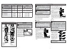
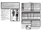
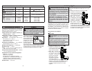
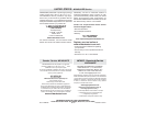
Resistance
1. Set the Dial to
position.
2. Connect the red test lead
to the V terminal and the
black test lead to the COM
terminal.
Confi rm “OL” is indicated on
the display, and then short-
circuit the tips of test leads to
make the indication zero.
3. Connect the test leads to
the both ends of the resistor
under test.
4. The reading is displayed.
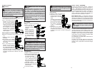
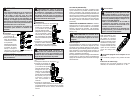
Continuity
1. Set the Dial to
position.
2. Connect the red test lead to the V terminal and
the black test lead to the COM terminal.
Confi rm “OL” is indicated
on the display, and then
short-circuit the tips of
test leads to make the
indication zero. A buzzer
will sound.
3. Connect the test leads
to the both ends of the
conductor under test. If
the resistance under test
is 30 or less, the buzzer
will sound.
DANGER To reduce the risk of
electric shock for Resistance, Continuity, and
Capacitance measurements, never use the
meter on an energized circuit. Make sure a
capacitor is fully discharged before touching
or attempting to make a measurement.
CAUTION After shorting the test
leads, the displayed value may not be zero due
to the resistance of test leads themselves.
CAUTION The Data Hold readings
are released when the meter enteres Sleep
Mode.
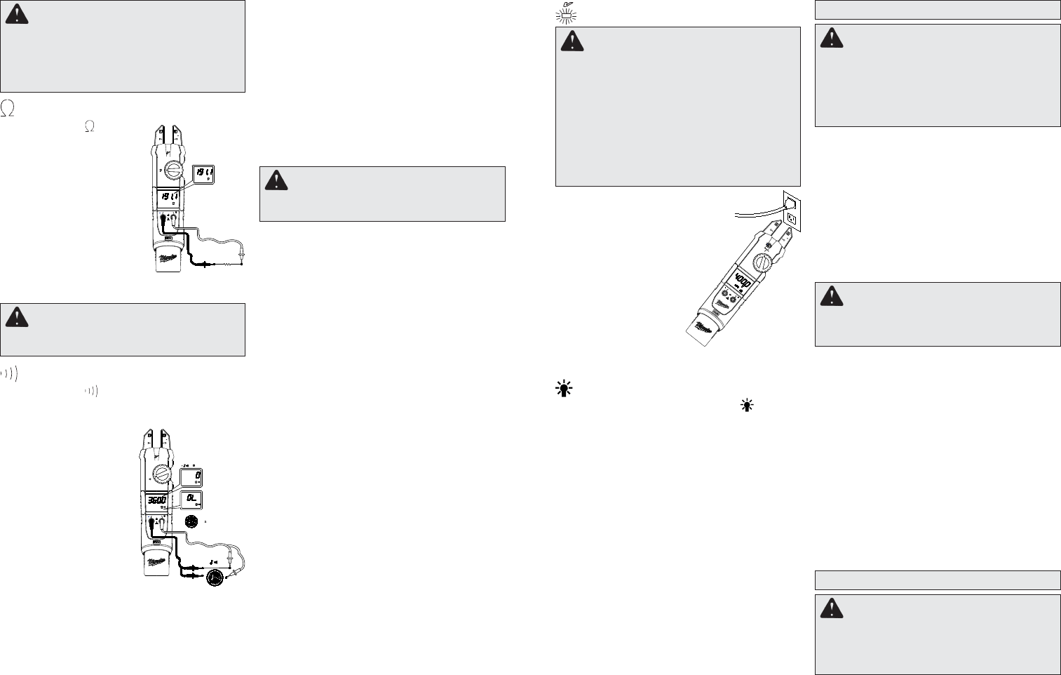
Non-Contact Voltage Detection (NCVD)
Sleep Mode
The meter is automatically powered off in about 20
min after the last Rotary Dial or button operation.
To reset, turn the Rotary Dial to OFF. If the display
is still blank when a new Rotary Dial setting is
selected, charge the battery.
The meter does use battery power in sleep mode.
Be sure to switch the tool to OFF to conserve bat-
tery power.
DANGER The LED may not be
displayed due to installation condition of
electrical circuit or equipment. Never touch
the circuit under test to avoid possible danger
even if the LED for NCVD is not displayed.
Check the functionality of LED on a well-
known power supply prior to measurement.
When the LED doesn’t light up, do not make
measurement.
NCVD indication is affected by external volt-
age, and how the meter is held or placed.
HOLD Key
Data Hold Function - Freezes the value on the
display. Press the “HOLD” button to freeze the
reading. The reading will be held regardless of
subsequent variation in input. HOLD is displayed
with the reading. To exit Data Hold mode, press the
HOLD button again.
SMART HOLD: The meter will beep continuously
and the display will fl ash if the measured signal is 50
counts larger than the display reading. (However,
it can not detect across the AC and DC Voltage/
Current)
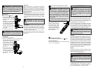
When the meter is on in
any function, the non-
contact voltage detector
will indicate with a Red
LED on the display when
an electric fi eld exceeding
90V is detected. Place the
edge of either the jaw near
the electric fi eld.
Worklight LED ON/OFF
To turn the light on and off, press the button.
Over-fl ow indication
Any time the input exceeds the measuring range
“OL” or “-OL” is displayed.
ACCESSORIES
For a complete listing of accessories refer to your
MILWAUKEE Electric Tool catalog or go online to
www.milwaukeetool.com. To obtain a catalog, con-
tact your local distributor or a service center.
WARNING Always remove battery
pack before changing or removing acces-
sories. Only use accessories specifically
recommended for this tool. Others may be
hazardous.
Maintaining Tool
Keep your tool, battery pack and charger in good
repair by adopting a regular maintenance program.
After six months to one year, depending on use,
return the tool, battery pack and charger to a
MILWAUKEE service facility service.
If the tool does not start or operate at full power
with a fully charged battery pack, clean the contacts
on the battery pack. If the tool still does not work
properly, return the tool, charger and battery pack,
to a MILWAUKEE service facility for repairs.
MAINTENANCE
Cleaning
Clean dust and debris from charger and tool vents.
Keep tool handles clean, dry and free of oil or grease.
Use only mild soap and a damp cloth to clean the
tool, battery pack and charger since certain cleaning
agents and solvents are harmful to plastics and other
insulated parts. Some of these include gasoline,
turpentine, lacquer thinner, paint thinner, chlorinated
cleaning solvents, ammonia and household deter-
gents containing ammonia. Never use fl ammable or
combustible solvents around tools.
Repairs
For repairs, return the tool, battery pack and char-
ger to the nearest service center listed on the back
cover of this operator's manual.
WARNING To reduce the risk of per-
sonal injury and damage, never immerse your
tool, battery pack or charger in liquid or allow
a liquid to fl ow inside them.
WARNING To reduce the risk of injury,
always unplug the charger and remove the
battery pack from the charger or tool before
performing any maintenance. Never disas-
semble the tool, battery pack or charger.
Contact a MILWAUKEE service facility for
ALL repairs.
_
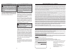
< 30
>250
M
C O
CAT.IV 600 V
CAT.III 1000 V
CAT.IV
1000 V
CAT.III
600 V
V
200 A
CAT.III 1000 V
CAT.IV
600 V
C
O
M
600 V
CAT.IV
1000 V
CAT.III
V
V
V
200 A
M
C O
CAT.IV 600 V
CAT.III 1000 V
CAT.IV
1000 V
CAT.III
600 V
V
200 A