


4
5
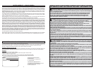
V
OFF
V
A
Lo-Z
CAT.III
1000 V
200 A
CAT.IV
600 V
mA
mF
HOLD
mV
ACDC
k
M
Z
AUTO
L
o
-
M
C O
V
CAT.IV 600 V
CAT.III 1000 V
HOLD
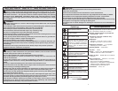
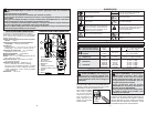
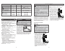
Dial Position Range Resolution Accuracy
Voltage DC/Voltage AC
400V
1000V
0.1V/1V
: ±(1.0% + 2 dgt)
: ±(1.5% + 5 dgt) 45-500 Hz
Lo-Z
Low Input Impedance
400.0V
1000V
0.1V/1V ±(2.0% + 3 dgt) AC:45~500Hz
Current AC 200A 0.1A ±(3.0% + 3 dgt) 45-60 Hz
Resistance
Continuity
400.0
4.000k
40.00k
400.0k
4.000M
40.00M
0.1
0.001k
0.01k
0.1k
0.001M
0.01M
±(1.0% + 5 dgt)
±(1.0% + 2 dgt)
±(1.0% + 2 dgt)
±(1.0% + 2 dgt)
±(1.0% + 2 dgt)
±(2.0% + 5 dgt)
Functions
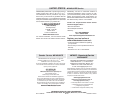
FUNCTIONAL DESCRIPTION
1. Light On/Off button
2. Hold button
3. Jaws
4. Light
4
2
1
3
6
7
5
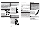
ASSEMBLY
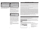
OPERATION
Before Use
Confi rm the Rotary Dial is set to the correct position,
the instrument is set to the correct measurement
mode, and the Data hold function is disabled. Oth-
erwise, desired measurement cannot be made.
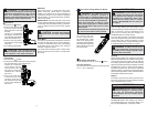
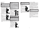
Making a Measurement
Voltage
DANGER To avoid electrical shock:
Never make measurement on a circuit in
which voltage over AC 1000V or DC 1000V
exists.
Keep fi ngers behind the guards and away
from test lead tips during measurements.
1. Set the Dial to
position.
2. Connect the red test lead
to the V terminal and the
black test lead to the COM
terminal.
3. AC: Connect the test leads
to the circuit under test. The
reading is displayed.
DC: Connect the red test
lead to the positive (+) side
and black test leads to
the negative (-) side of the
circuit under test. The reading is displayed. A
reversed connection is indicated as a negative
value.
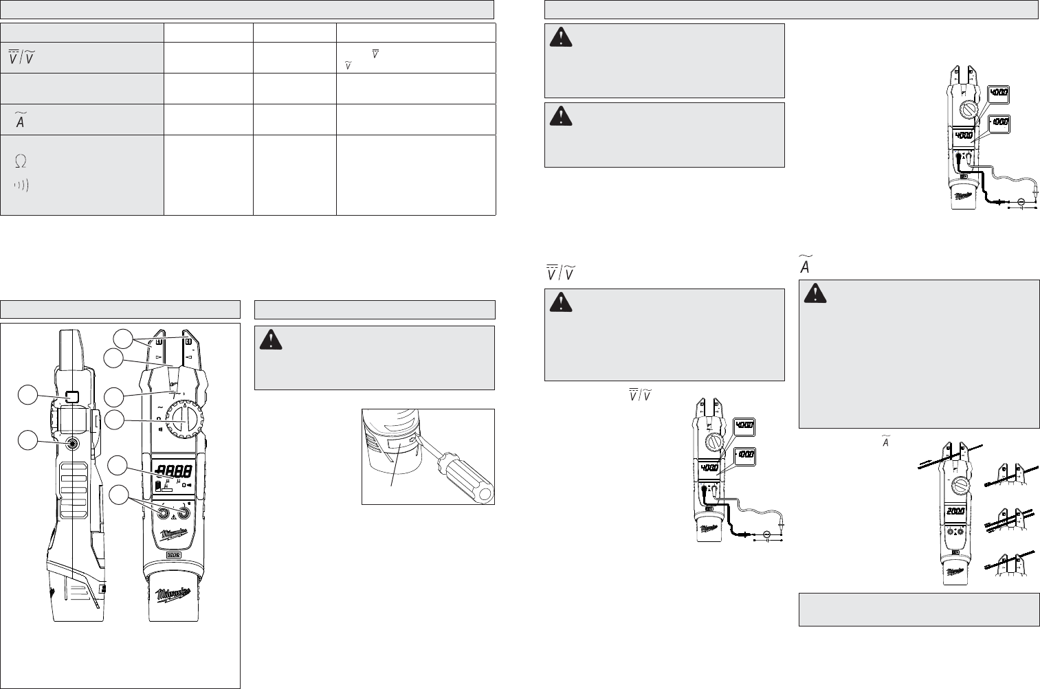
1. Set the Dial to
position.
2. Run the conductor
through the jaws. The
reading is displayed.
NOTE: Do not place
2 or more wires be-
tween jaws at the
same time. Place
wire between arrows.
Otherwise, irregular
results will occur.
CAUTION Maximum conductor size is
approx 5/8” diameter.
DANGER To avoid electrical shock:
Never make measurement on a circuit in
which voltage over AC 1000V or DC 1000V
exists. Jaws are designed not to short the
circuit under test. If equipment under test has
exposed conductive parts, however, extra
precaution should be taken to minimize the
possibility of shorting.
Disconnect the test leads from the instrument
for current measurement.
Lo-Z Low Input Impedance
Automatic voltage detection (AC or DC).
1. Set the Dial to Lo-Z position.
2. Connect the red test lead
to the V terminal and the
black test lead to the COM
terminal.
3. AC: Connect the test leads
to the circuit under test. The
reading is displayed.
DC: Connect the red test
lead to the positive (+) side
and black test leads to the
negative (-) side of the cir-
cuit under test. The reading is displayed. A
reversed connection is indicated as a negative
value.
Current
WARNING Only use MILWAUKEE test
leads with the MILWAUKEE Fork Meters.
Inspect test leads before each use. Use meter
to run a continuity test.
WARNING Recharge only with the char-
ger specifi ed for the battery. For specifi c charg-
ing instructions, read the operator’s manual
supplied with your charger and battery.
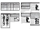
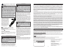
Inserting/Removing the Battery
To remove the bat-
tery, use a fl at screw-
driver to pry open the
lock latch. Push in the
release buttons and
pull the battery pack
away from the tool.
To insert the battery,
slide the pack into the body of the tool. Make sure
it latches securely into place. Press in the lock latch
to lock the battery in place.
Lock latch
Fig. 1
WARNING Always turn the Rotary
Dial to OFF before inserting or removing
probes. Only use accessories specifi cally
recommended for this tool. Others may be
hazardous.
A
AC
CAT.III 1000 V
CAT.IV 600 V
V
OC
M
600 V
CAT.IV
200 A
1000 V
CAT.III
A
200A
CAT.IV
600 V
200 A
CAT.III
1000 V
CAT.IV
600 V
200 A
CAT.III
1000 V
600 V
CAT.IV
200 A
1000 V
CAT.III
3
2
2
AUTO
AC
V
AC
AUTO
V
DC
AUTO
V
ACV
DCV
CAT.III 1000 V
CAT.IV 600 V
OC
M
V
CAT.III
1000 V
CAT.IV
600 V
V
V
200 A
AUTO
AC
V
AC
AUTO
V
DC
AUTO
V
ACV
DCV
CAT.III 1000 V
CAT.IV 600 V
OC
M
CAT.III
1000 V
CAT.IV
600 V
V
200 A
Lo-Z
Z
L
o
-
Z
L
o
-
Z
L
o
-
8
5. NCV indicator
6. Dial
7. Display
8. Terminal inputs