


4
5
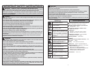
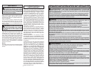
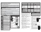
Dial Position Range Resolution Accuracy
Voltage AC/DC
400V
1000V
0.1V/1V
: ±(1.5% + 5 dgt) 45-500 Hz
: ±(1.0% + 2 dgt)
Current AC 200A 0.1A ±(3.0% + 3 dgt) 45-60 Hz
Resistance
Continuity
400.0
4.000k
40.00k
400.0k
4.000M
40.00M
0.1
0.001k
0.01k
0.1k
0.001M
0.01M
±(1.0% + 5 dgt)
±(1.0% + 2 dgt)
±(1.0% + 2 dgt)
±(1.0% + 2 dgt)
±(1.0% + 2 dgt)
±(2.0% + 5 dgt)
Capacitance (2206-20)
1000F1F
±(1.9% + 2 dgt)
100.0F 0.1F
Current DC (2206-20)
400.0A
1000A
0.1A ±(1.0% + 2 dgt)
Temperature C° / F°
(2206-20)
-40ºC ~ 400ºC
-40ºF ~ 752ºF
0.1°C
0.2°F
C°:±(1% + 2C°)
F°:±(1% + 3 F°)
Lo-Z
Lo-Z
Low Input Impedance
(2205-20)
400.0V
1000V
0.1V/1V ±(2.0% + 3 dgt) AC:45~500Hz
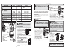
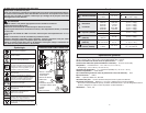
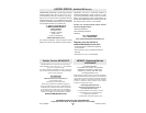
Functions
FUNCTIONAL DESCRIPTION
1. Light On/Off button
2. Hold button
3. Jaws
4. Light
5. NCV indicator
6. Dial
7. Display
8. Terminal inputs
4
2
1
3
6
7
8
Cat. No.
2206-20
Lo-Z
6
Cat. No.
2205-20
5
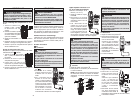
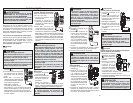
ASSEMBLY
Selecting C° or F°
1. Turn Rotary Dial to OFF and
disconnect the test leads.
2. Unscrew and remove bat-
tery door and remove any
installed batteries.
3. Set the C°/F° switch to the
desired position.
4. Replace batteries according
to “Loading/Changing the Batteries.
5. Close the battery door and tighten screw se-
curely.
Loading/Changing the Batteries
Replace batteries when the Low
Battery indicator is displayed.
1. Turn Rotary Dial to OFF and discon-
nect the test leads.
2. Unscrew and remove battery door.
3. Insert two (2) AA batteries, according
to the polarity marked in the battery
compartment
4. Close the battery door and tighten screw
securely.
WARNING
To avoid an electrical hazard, turn the Rotary
Dial to OFF and disconnect the test leads
before opening battery compartment or
replacing batteries.
OPERATION
Before Use
Confi rm the Rotary Dial is set to the correct position,
the instrument is set to the correct measurement
mode, and the Data hold function is disabled. Oth-
erwise, desired measurement cannot be made.
LCD Backlight
The LCD backlight will turn off after about 3 minutes
of inactivity. Push any button or turn the rotary dial
to turn the backlight on.
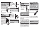
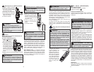
Making a Measurement
Voltage
DANGER
To avoid electrical shock:
Never make measurement on a circuit in
which voltage over AC 1000V or DC 1000V
exists.
Do not use with the Battery Cover removed.
Keep fi ngers behind the guards and away
from test lead tips during measurements.
1. Set the Dial to
posi-
tion.
2. Connect the red test lead
to the V terminal and the
black test lead to the COM
terminal.
3. AC: Connect the test leads
to the circuit under test. The
reading is displayed.
DC: Connect the red test
lead to the positive (+)
side and black test leads
to the negative (-) side of
the circuit under test. The
reading is displayed. A reversed connection is
indicated as a negative value.
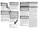
Current
1. Set the Dial to
position.
2. Run the conduc-
tor through the
jaws. The read-
ing is displayed.
NOTE: Do not
place 2 or more
wires between
jaws at the same
time. Place wire between arrows. Otherwise,
irregular results will occur.
CAUTION
Maximum conductor size is approx 5/8”
diameter.
DANGER
To avoid electrical shock:
Never make measurement on a circuit in
which voltage over AC 1000V or DC 1000V
exists. Jaws are designed not to short the
circuit under test. If equipment under test has
exposed conductive parts, however, extra
precaution should be taken to minimize the
possibility of shorting.
Do not use with the Battery Cover removed.
Disconnect the test leads from the instrument
for current measurement.
Correct
Incorrect
Incorrect
Lo-Z Low Input Impedance
(Cat. No. 2205-20 only)
Automatic voltage detection
(AC or DC).
1. Set the Dial to Lo-Z posi-
tion.
2. Connect the red test lead
to the V terminal and the
black test lead to the COM
terminal.
3. AC: Connect the test leads
to the circuit under test. The
reading is displayed.
DC: Connect the red test
lead to the positive (+) side
and black test leads to the negative (-) side of
the circuit under test. The reading is displayed.
A reversed connection is indicated as a negative
value.
WARNING
Only use MILWAUKEE test leads with the
MILWAUKEE Fork Meters.
Inspect test leads before each use. Use me-
ter to run a continuity test.