


201/203 Series Page 18 of 20
Orifice Changes:
A) Determine the minimum expected upstream pressure (Pu) in PSI absolute and the maximum
expected downstream pressure (Pd) in PSI absolute for full flow conditions.
B) If Pu >2Pd, use formula 1; otherwise use formula 2.
Where:
Formula 1: Formula 2:
Q
P
D
σ
μ
0028.0
=
Q
d
D
0014.0
σ
Ρ•ΔΡ
=
D = Diameter in inches
Q = Flow rate in standard liters per minute
P = Pu - Pd in PSI
Pu = Upstream pressure in PSIA
Pd = Downstream pressure in PSIA
σ
= Specific gravity of gas
Choose the orifice form Section 5.0 that has the closes larger diameter to the calculated diameter.
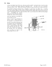
4.7.1. HFC-203 Orifice
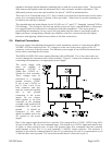
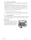
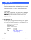
To change the orifice in the HFC-203 unit, the valve must be dismantled. Remove the four 1/4"
Allen head machine screws in the top of the main valve. Lift off the valve top, exposing the spring
and diaphragm. Note that a small brazed ball bearing is on the down stream side of the valve top.
Remove the spring and diaphragm assembly. The orifice is located in the bottom of the valve body
and can be removed with a 9/16 socket wrench. See Figure 4.5.
To reinstall an orifice, first install the gasket onto the orifice (replacement gaskets can be obtained
from the factory). Next screw the orifice into the valve base. Snug up the orifice but do not over
tighten. Place diaphragm assembly into the base. Line up the two small holes in the diaphragm with
the two small holes in the valve base. Place the
spring on top of the diaphragm. Examine the o-
ring on the valve top for damage if required. Install
the valve top, ensuring that the ball bearing in the
side is on the downstream side. Tighten down the
valve top evenly to insure a proper seal at the
diaphragm.
4.8. Replacement Parts
The following is a list of the available replacement
parts and their factory stock numbers. The HFM-
201 and the HFC-203 shunts and filter discs are
interchangeable. The same sensor module is used
on all models. All HFM models use the same
printed circuit board.
FIG 4.5