


201/203 Series Page 12 of 20
3. Theory of Operation
This section contains an overall functional description of HFC Flow Controllers. Detailed
schematics and parts lists can be found at the end of the manual in Section 6.0. In this section and
other sections throughout this manual, when a power supply is mentioned, it is assumed that the
customer has a Hastings Power Supply. These sections are not applicable if another type of power
supply is used.
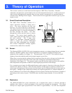
3.1. Overall Functional Description:
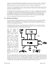
The HFC Flow Controller consists of a
sensor, electronic circuitry, a shunt and a
valve. The sensor measures the flow rate
from 0 to 10 sccm of the gas to be metered.
The shunt divides the flow such that the flow
through the sensor is a precise percentage of
the flow through the shunt. The flow
through the sensor and the shunt is always
laminar. The circuit board amplifies the
sensor output and uses this output to control
the valve position. The 2 stage valve
employs an automatic metering solenoid,
used to control the pressure differential
across the main diaphragm seat assembly.
All of these components working together
result in a fast, stable flow controller.
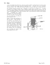
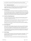
3.2. Sensor:
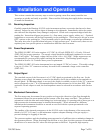
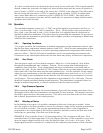
The Hastings HFM-201/HFC-203 series instruments operate on a unique thermal electric principle
whereby a metallic capillary tube is heated uniformly by a resistance winding attached to the
midpoint of the capillary (see Figure 3.1). Thermocouples TC-1 and TC-2 are welded at equal
distances from the midpoint and develop equal outputs at zero flow.
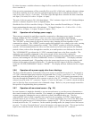
When flow occurs through the tubing, heat is transferred from the tube to the gas on the inlet side,
and from the gas back to the tube on the outlet side creating an asymmetrical temperature
distribution (sees Figure 3.2). The thermocouples sense this decrease and increase in the capillary
tube temperature and produce a millivolt output signal proportional to that change.
For a constant power input, the differential thermocouple output is a function of the mass flow rate
and the heat capacity of the gas. Since the heat capacity of many gases is relatively constant over
wide ranges of temperature and pressure, the flow meter may be calibrated directly in mass units for
those gases. Changes in gas composition usually only require application of a simple multiplier to
the air calibration to account for the difference in heat capacity and thus the flow meter is capable of
measuring a wide variety of gases. The HFM sensor measures approximately 10 sccm, full scale
flow.
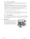
3.3. Electronics:
The HFM-201/HFC-203 series instruments use a thermal flow sensor to measure through a
capillary tube, which is a fixed percentage of the total flow through the instrument. This sensor
develops an output signal proportional to flow which is approximately 1 mv full scale magnitude.
FIG 3.1