


201/203 Series Page 17 of 20
4) Set command to 100%. Adjust SPAN (R29) pot until the flow reference reads full scale flow (5.000
VDC). NOTE: Perform this step only if a calibrated reference flow meter is available.
5) Record flow meter and flow reference outputs for flow rates of 20%, 40%, 60%, 80% and 100%.
4.3.2. Miscellaneous adjustments
Periodically, during normal operation, the ZERO should be checked and adjusted when required. If
system parameters change, the RESPONSE pot may require a small adjustment for optimum
stability. If the instrument is not shutting completely off when Valve Override switch is in the
CLOSE position, the orifice may require approximately 1/8 turn clockwise.
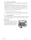
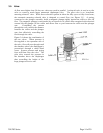
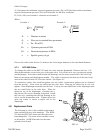
4.4. End Cap Removal:
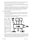
The end cap on the inlet side must be removed to gain access to the filter or shunt assembly. First
shut off the supply of gas to the instrument. Disconnect the Swagelok fitting on the inlet and outlet
sides of the transducer, and remove it from the system plumbing. Remove the four hex bolts holding
the end cap to the instrument (see Figure 4.1). Carefully remove the end cap, filter, wave spring (if
present) and shunt, noting their order and proper orientation. The shunt can be severely damaged if
dropped. Examine the filter and shunt. If either is dirty or blocked, clean or replace as applicable.
Reassembly is the reverse of the removal procedure. Recalibration of the HFC is necessary.
4.5. Printed Circuit Board Replacement
In the unlikely event that the PC board fails, it is easily removed from the instrument and replaced
with a spare to minimize instrument downtime. Replacement of the PC board will require the
instrument to be recalibrated per Section 4.4.1.
Unplug the power cable from the top of the transducer. Remove the two jackscrews next to the “D”
connector and the two screws on the sides of the cover. Lift off the cover and unplug the four-wire
sensor plug and the two wire valve plug, noting their orientation prior to removal.
Remove the screw that holds the PC board to the sensor. Troubleshoot or replace as applicable.
Installation is the reverse of the above procedure. Recalibrate if any components were changed or if
any potentiometers were adjusted.
4.6. Sensor Replacement:
If the sensor fails or becomes plugged it can be removed. Remove the cover and the PC board per
Section 4.7 above. Remove the three bolts holding the sensor to the instrument base. Remove the
sensor from the base noting the two O-rings (Parker 2-005, V884-75) between the sensor and the
base. If the sensor is plugged it can be cleaned by running a fine wire (approximately 0.008"
diameter) through the tube. If sensor needs replacement, obtain another from the factory and install
it. Ensure that O-rings are clean and intact. Install O-rings on seating surface, then carefully place
sensor over O-rings and tighten down the three screws evenly. Replacement of sensor will require
recalibration per Section 4.3.1.
4.7. Orifice Changes:
The orifice may require replacement if a flow range change is desired, if a large change in differential
pressures across the valve is desired or in the event that a small orifice becomes plugged.
Replacement orifices can be acquired from the factory. See Section 4.8 for the list of standard
orifices and their flow rates in air.
When using nonstandard pressures or gases that have specific gravities different than air (such as
hydrogen or helium), the diameter of the orifice must be calculated using the following procedure: