


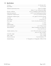


201/203 Series Page 15 of 20
4. Maintenance
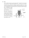
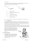
This section contains service and calibration information. Some portions of the instrument are
delicate. Use extreme care when servicing the flow controller. The potentiometer positions and the
electrical components referred to in the troubleshooting section can be found in Section 6.0 on the
electrical component layout drawing.
4.1. Authorized Maintenance
With proper care in installation and use, the flow controller will require little or no maintenance. If
maintenance does become necessary, most of the instrument can be cleaned or repaired in the field.
Some procedures may require recalibration. Do not attempt these procedures unless facilities are
available. Entry into the sensor or tampering with the printed circuit board will void warranty. Do
not perform repairs on these assemblies while unit is still under warranty.
4.2. Troubleshooting
SYMPTOM: Output reads 40% of flow with no flow. Zero pot has no effect.
CAUSE: Power supply locked up or shorted out.
ACTION: Turn off power supply for a few seconds, then turn back on. If this proves ineffective,
disconnect the unit from the power supply. If power supply display does not return to zero, then a
regulator chip in the power supply is probably burned out. Check supply voltages and replace faulty
regulator. If display returns to zero after disconnecting the power supply from the unit there is a
short in the unit to ground. Check capacitors C10 & C11 first.
SYMPTOM: Override switch is in CLOSE position, but flow remains or 0.00 VDC is commanded
and flow remains.
CAUSE: Orifice out of adjustment or faulty op-amp
ACTION: Check valve voltage at connector pins TP-3 & TP-6. If voltage is less than 3.00 VDC,
then turn orifice clockwise until flow stops. If voltage is greater than 3.00 VDC. If they are greater,
replace U1; if less, replace transistor Q1.
SYMPTOM: Output of unit is proportional to flow but extremely small and not correctable by span
pot.
CAUSE: Sensor is not being heated.
ACTION: Unplug connector J2. Check the following resistance: The resistance between pins 2 &
3 of the sensor should be approximately 2500 ohms (see Figure 3.1 on page 8). The resistance
between pins 1 & 4 should be approximately 2.3 ohms. The resistance between pins 2 & 3 and the
base of the sensor should be essentially infinite. If not, replace the sensor unit. If sensor reads O.K.,
check the voltage output on pins 2 & 3 of the jack in the board. If it does not read approximately 22
VDC then replace op-amp U2.
SYMPTOM: Sensor has proper resistance readings, but little or no output with flow.
CAUSE: Plugged sensor.