


201/203 Series Page 10 of 20
B, it then becomes a variable reference voltage for flow controller B proportional to the flow rate of
flow controller A.
If the set point potentiometer of flow controller B is set at 50% of full scale, and the reference voltage
from flow controller A is 4.00, then the command signal going to flow controller B would be 2.00
volts (4.00 volts x 50.0% = 2.00 volts). The flow of gas through flow controller B is then controlled
at 4 slpm (2.00 volts/5.00 volts x 10 slpm = 4 slpm).
The ratio of the two gases is 20:1 (80 slpm/4slpm). The % mixture of gas A is 95.2 (80slpm/84slpm
and the % mixture of gas B is 4.8% (4 slpm/84 slpm).
Should the flow of flow controller A drop to 78 slpm, flow controller B would drop to 3.9 slpm,
hence maintaining the same ratio of the mixture. (78 slpm/100slpm x 5v = 3.90v x 50% = 1.95v;
1.95v/5.00v x 10 slpm = 3.9 slpm; 78 slpm:3.9 slpm = 20:1)
2.6.5. Operation with a Hastings power supply.
There are two controls for each flow controller connected to a Hastings power supply. A switch
labeled “OPEN; AUTO; CLOSED” (valve over ride) and a potentiometer knob labeled
“COMMAND”. For normal operation, the valve over ride switch will be in the “AUTO” position.
The “CLOSE” position removes all power from the valve, shutting off flow regardless of the
command pot setting. The “OPEN” position applies full available valve voltage to the valve, causing
it to open, regardless of the command pot setting. The “OPEN” position is useful for purging
systems. It is recommended that the valve over ride switch not be left in this position for extended
periods of time, with no flow through the controller, as a small positive zero shift may be observed.
The “COMMAND” pot adjusts the 0-5 VDC command signal sent to the flow controller. The
setting for each controller connected to the power supply can be observed by rotating the
“POWER/CHANNEL SELECT” knob to the channel connected to the controller that you wish to
observe, and rotating the “FLOW/COMMAND” knob to “COMMAND”. The display will then
indicate the command signal. (Depending on how the power supply was set up, the display could
indicate in flow units or percent of full scale.) To observe the flow output of the flow controller,
rotate the “FLOW/COMMAND” knob to “FLOW”. The display will now indicate the flow output
signal.
2.6.6. Operation with a power supply other than a Hastings.
The flow controller must be connected to the power source as specified in section 2.6. In general, a
0-5 VDC command signal proportional to the intended flow (0 volts = zero flow; 5 volts = 100% of
rated flow) must be applied to pin 14 of the “D” connector. A 0-5 VDC signal proportional to the
flow rate through the instrument will be present on pin 6 of the “D” connector. The control mode is
selected via pin 8 of the “D” connector. Apply +15 volts for full open, -15 volts for closed and allow
pin 8 to float for flow proportional to the command voltage. Refer to your power supply manual for
the specifics of implementing these parameters.
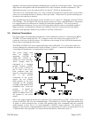
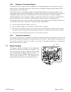
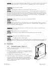
2.6.7. Operation with an external sensor. (Fig. 2.2)
In some instances, it might be desirable to use an external sensor to provide process information to
the control circuitry in the flow controller. For example, you might want to control the pressure in a
vacuum system by adjusting the rate at which the system is backfilled with a gas. The new,
enhanced HFC series of flow controllers have provision for accepting a 0-5VDC output from an
external sensor at pin 13 of the “D” connector. To activate this feature, the cover of the HFC must
be removed to gain access to PC-828 and move a jumper on JP1. JP1 is a three pin jumper block
located just below the “D” connector. In the normal operating mode, the jumper covers the bottom
two pins. To select “External Sensor”, move the jumper to the upper two pins. This swaps the flow
input to the controller circuit from the flow meter output to pin 13 of the “D” connector.