


7-9C
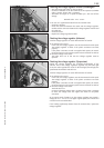
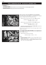
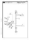
Static ignition values 250 MXC, EXC USA
Check the pulse generator for an output signal – two one-pin connectors
1 with green and red cable colors (also see circuit diagram on opposite
page):
– Apply the red measuring lead of the peak voltage adapter to the green
cable and the black measuring lead to the red cable, disconnect both
connectors
1 to disconnect the CDI unit 2
Multimeter display: 3.5 volts +/- 1 volt
– Same measurement with CDI unit connected
Multimeter display: 2 volts +/- 0.5 volt
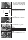
Check the generator charging coil for ignition capacitor charge for out-
put voltage – two-pin connector
3 with black/red and red/white cable
colors (also see circuit diagram on opposite page)
– apply the red measuring lead of the peak voltage adapter to the
black/red cable and the black measuring lead to the red/white cable,
disconnect connector
3 to disconnect the CDI unit 2
Multimeter display: 45 volts +/- 5 volts
– Same measurement with connectors CDI unit connected
Multimeter display: 220 volts +/- 10 volts
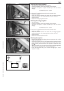
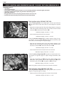
Check the primary voltage output
4 for ignition coil control (also see cir-
cuit diagram on opposite page) for output voltage (blue/white cable
color):
– apply the red measuring lead
R of the peak voltage adapter to the
black/white cable (ground) and the black measuring lead
S to the
blue/white cable, CDI unit
2 and ignition coil 5 connected
Multimeter display: 210 volts +/- 10 volts
NOTE: the ignition coil does not need to be removed to measure.
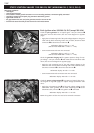
Static generator values 250 MXC, EXC USA
Check the generator output 6 for the lighting system (also see circuit
diagram on opposite page) for voltage:
– between yellow and brown (ground), connector disconnected
Multimeter display: 10.5 volts +/- 1 volt
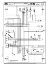
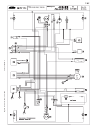
STATIC IGNITION AND GENERATOR VALUES 250 MXC, EXC USA
(KOKUSAN 2K-2)
Measuring conditions:
– cold engine
– seat and tank removed
– all connectors and the ground connection in a non-corroding condition, connectors tightly connected
– spark plug screwed out and spark plug connector attached to ground
– light switch turned off
– the gap between the rotor and pulse generator must be set to 0.75 mm
– kick the kick starter forcefully at least 5 times for each measurement
3
5
4
S
R
1
1