


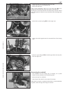

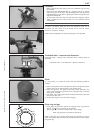
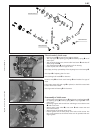
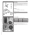
– Place preassembled control flap in cylinder, engage gear segments in
control rollers in such a manner that, when the control flap is ,open
(pivoted right to the top), the markings of the gear segments and the
gear rollers coincide. Please check that the two control rollers do not
block the cross-section of the port when the control flap is open.
– Coat sealing surface thinly with silicon and mount intermediate flange
bs with 4 O-rings (11,3x2,4 mm).
– Mount exhaust flange
bt and spring hangers. If you are dealing with
a throttled version, do not forget the exhaust throttle.
– Finally check smooth running of exhaust control system.
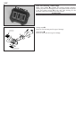
NOTE: It must be possible to push adjusting lever
bl further upwards
against the spring force.
5-7C
16
17
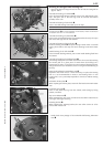
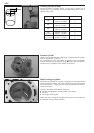
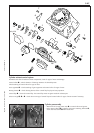
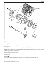
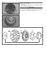
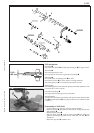
–Mount and grease silicon O-rings (15x1,50 mm) 9 on control flap and grease.
– Slightly grease the bearing sleeves 3 and plug them on the control flap.
– Mount toothed segments
2 (the toothed segment with the cylindrical pin has to be mounted on the right side).
– On the right-hand side, mount bearing bushing
bk with collar outside, adjusting lever bl with ball head on outside, overload
spring
bm with short leg on outside and spring sleeve bn to control flap.
– Coat allan head screw
bo with Loctite 243 and screw up about 5 revolutions, hook the short leg of the overload spring on to the
cylinder pin (see illustration) and tighten the allan head screw.
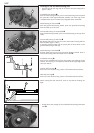
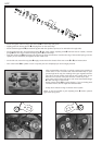
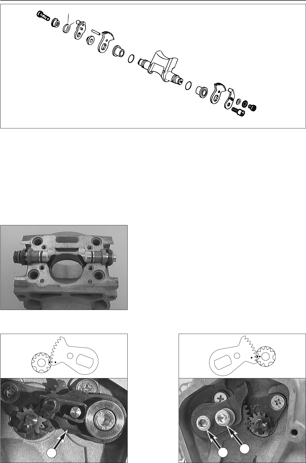
– On the left side, mount the stop plate
8. Apply Loctite 243 to the threads of the two screws bq + br, and mount them.
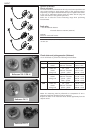
–Turn control rollers
1 in cylinder in such a way that ports are completely open and no edges protrude.
14
13
12
11
10
2
3
9
4
9
3
2
8
16
17
11