


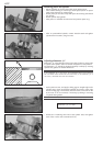
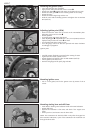

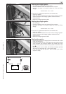
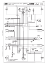
Checking the capacitor
– Discharge the capacitor by bridging the two terminals with a
screwdriver and remove.
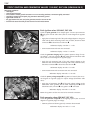
– Connect the negative pole of a 12V battery with the negative terminal
of the capacitor. The connection between the positive pole of the
battery and the positive terminal of the capacitor (marked +) is made
with a test lamp
1.
– When the power circuit is closed, the test lamp must begin to light up.
As capacitor charging increases, the brightness of the test lamp must
decrease.
– The test lamp must go out after 0,5-2 seconds (depending on the lamp
capacity).
– If the test lamp does not go out or does not light up at all, the
capacitor is faulty.
!
CAUTION
!
DISCHARGE THE CAPACITOR BEFORE AND AFTER EACH TEST.
W
HEN INSTALLING THE CAPACITOR
, MAKE SURE THAT THE TERMINALS ARE CONNECTED
IN ACCORDANCE WITH THEIR MARKINGS
(CONNECT RED/WHITE CABLE TO +
TERMINAL).
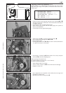
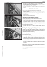
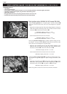
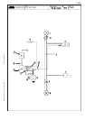
Ignition coil (SEM)
As this ignition coil uses electronic components, you are advised not to
use conventional measuring instruments. An accurate function test can
only be carried out on an ignition test bench.
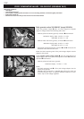
Ignition coil (Kokusan)
– Disconnect all cables and remove the spark plug connector.
– Use an ohmmeter to measure the following values.
NOTE: The indicated setpoint values correspond to a temperature
of 20° C.
Replace the ignition coil if the measured values deviate significantly from
the setpoint values.
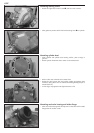
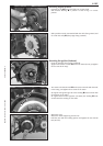
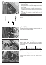
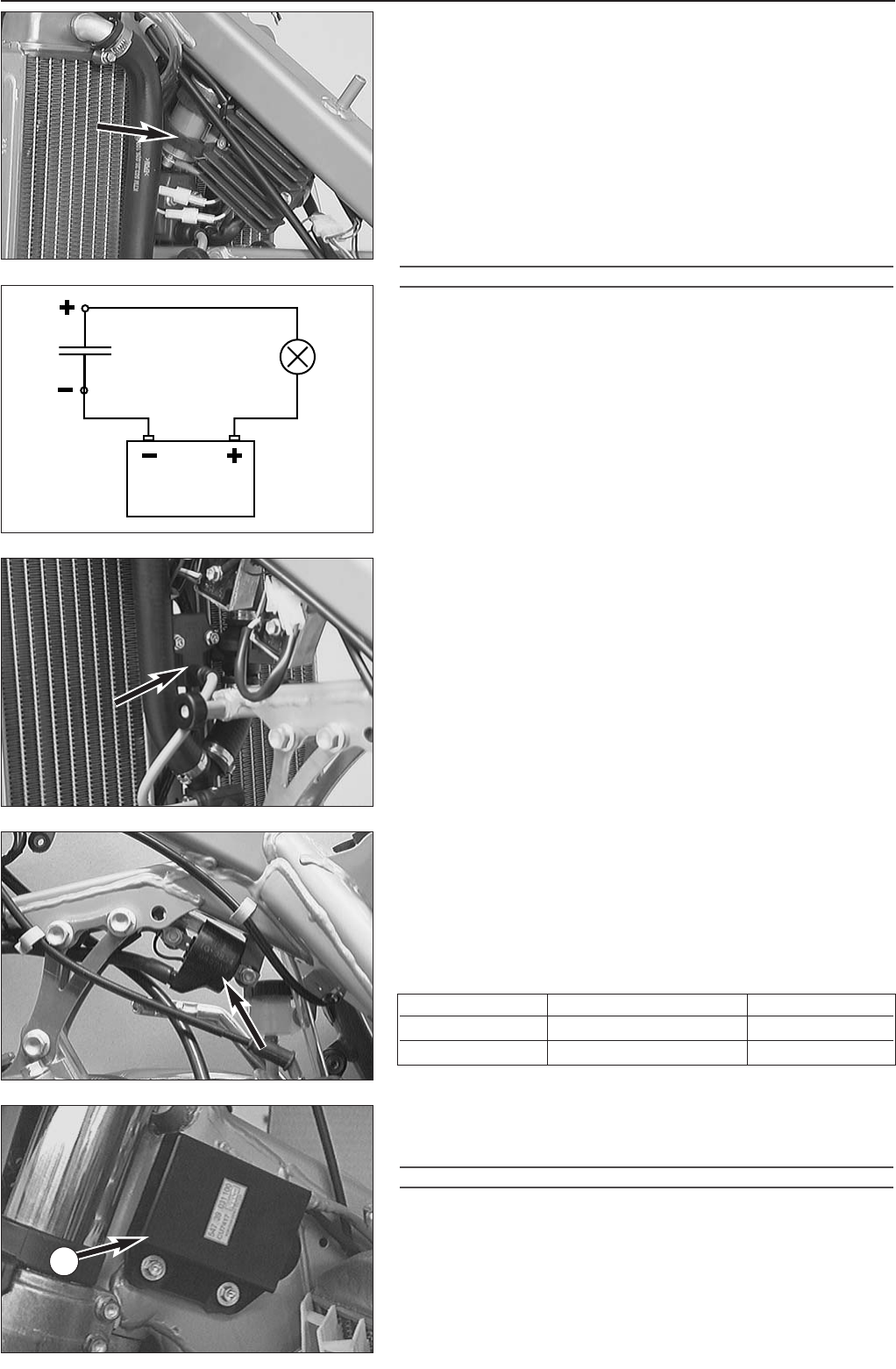
CDI unit
Check the cables and plug and socket connections of the CDI unit 2.
The CDI unit function can only be checked on an ignition test bench.
!
CAUTION
!
N
EVER USE A COMMERCIAL MEASURING DEVICE TO CHECK THE CDI UNIT.
C
OMMERCIAL MEASURING DEVICES CAN DESTROY HIGHLY SENSITIVE ELECTRONIC
COMPONENTS
.
7-3C
Measurement Cable colours Resistance
Primary coil blue/white – ground 0,425 - 0,575 Ω
Secondary coil blue/white – ignition wire 10,8 - 16,2 kΩ
1
2