


8
Getting Started
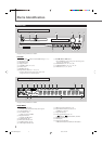
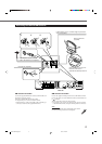
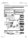
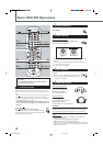
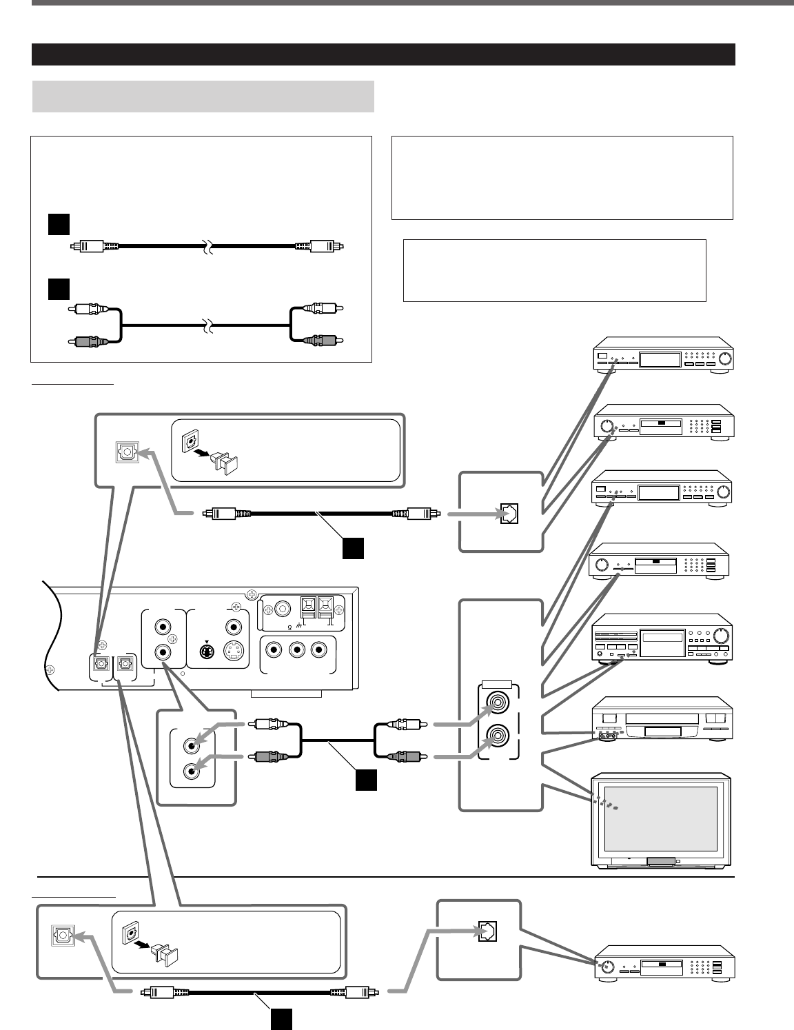
Connecting Audio/Video Component
Turn the power off to all components before connections.
ANALOG VIDEO OUT
COAXIAL
FM 75
AM LOOP
YP
B
P
R
AM
EXT
VIDEO
S-VIDEO
IN
L
R
DIGITAL
IN
DIGITAL
OUT
AUX
OPTICAL
A
N
T
E
N
N
A
CONPONENT VIDEO OUT
DBS Tuner
Center unit
MD Recorder
Cassette Deck
OUT
LEFT
RIGHT
AUDIO
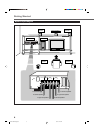
VCR
TV
MD Recorder
DIGITAL
OPTICAL OUT
A
B
DIGITAL
IN
ANALOG
IN
L
R
DBS Tuner
MD Recorder
DIGITAL
OPTICAL IN
A
DIGITAL
OUT
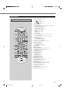
Before connecting an
optical digital cord, unplug
the protective plug.
Illustrations of the input/output terminals below are typical
examples.
When you connect the other component, refer also to its
manuals since the terminal name actually printed on the rear
vary among the components.
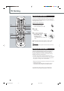
If you connect a sound-enhancing device such as a graphic
equalizer between the source component and the center
unit, the sound output through this system may be
distorted.
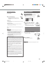
Connect the other component to the center unit with the
audio cord.
Use the cords supplied with the other component or
purchase them at an electric appliance store.
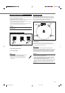
Optical digital cord (not supplied)
Audio cord (not supplied)
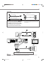
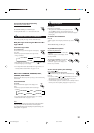
Audio Component connection
A
B
• If you use the OPTICAL DIGITAL OUT to connect the external component, you
select the output signal type correctly. See “Audio Menu” on page 53.
Output Terminal
Input Terminals
Before connecting an
optical digital cord, unplug
the protective plug.
EN01-09TH-A35[A].pm6 03.5.12, 7:25 PM8