7
use Blue Loctite #242 on the spindle
nut. The diaphragm is to be assembled
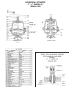
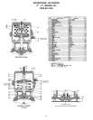
top hat up. See Table 1 for fastener
torques.
3.8.4 Spindle O-Ring Replacement (All sizes)
3.8.4.1 Disconnect air lines. Remove actuator
from valve body and dismantle actua-
tor following instructions above for
removing actuator diaphragm and
spring.
3.8.4.2 Withdraw valve diaphragm, compres-
sor and spindle assembly from the
bonnet.
3.8.4.3 Replace o-rings and reassemble by
reversing the instructions and follow-
ing the steps for replacing a valve
diaphragm. Care must be used on the
Bio-Tek
®
to align the compressor T-slot
with molded tabs in lower cover.
Lubricate o-rings prior to installation
per Section 3.4.
4 ACCESSORIES
4.1 Travel (Closing) Stop Adjustment
This feature is standard on 3” - 4” Series 47 (DIN
80-100) actuators and optional on the 1/4” - 2” (DIN
8-50). It is not available on 3” - 4 “ Series 33 (DIN
80-100).
The purpose of the travel stop is to prevent over-
loading of the diaphragm, thus prolonging
diaphragm life. Travel stops are factory set and
do not require routine adjustment. However, with
replacement of valve diaphragms, travel stop
adjustment is recommended.
4.1.1 All Operating Modes:
4.1.1.1 Remove switch Package if present.
4.1.1.2 Release air pressure in actuator covers.
4.1.1.3 Remove clear plastic cap.
4.1.1.4 To adjust travel (closing) stop, first
loosen jam nuts and back off one turn.
If double or direct acting, apply
enough pressure in top cover to close
the valve. While preventing the adjust-
ing bushing from rotating, turn lower
nut clockwise until valve leaks. Then
turn lower nut counterclockwise until
valve stops leaking while continuing to
insure the adjusting bushing does not
rotate. Tighten jam nuts together, the
travel stop is now set. Replace plastic
cap.
4.2 Combination Manual Over-ride (Open) and
Adjustable Opening Stop
(Manual Over-ride (Open) not available on 1/4”
through 2”, DIN 8 - 50 or 3” & 4”, DIN 80 - 100
Series 33.)
4.2.1 Operation of Manual Over-ride (Open): (3” &
4” Series 47 only, DIN 80 & 100 only)
4.2.1.1 Remove switch Package if present.
4.2.1.2 Release any air pressure in top cover.
4.2.1.3 Remove clear plastic cap and loosen
jam nuts.
4.2.1.4 Use a wrench to hold the adjusting
bushing from rotating, turn the lowest
jam nut clockwise. This opens the valve
0.056” (1.42 mm) per rotation. Rotate
the nut counterclockwise to return
valve to closed position. Note: Travel
stop adjustment is recommended at
this time. See Section 4.1 to adjust
travel stop.
4.2.1.5 Tighten jam nuts together and assem-
ble plastic cap.
4.2.2 Operation of Adjustable Opening Stop:
(1/4” through 2”, DIN 8 - 50)
4.2.2.1 Remove switch package if present.
4.2.2.2 Using air pressure and bleed type regu-
lator, open valve to desired position.
4.2.2.3 Rotate adjusting bushing counterclock-
wise until resistance is felt.
4.2.2.4 Opening stop is now set. NOTE: VALVE
CLOSED SWITCH REQUIRES ADJUST-
MENT.
4.2.3 Operation of Adjustable Opening Stop:
(3” & 4” Series 47, DIN 80 & 100)
4.2.3.1 Remove switch package if present.
4.2.3.2 Remove clear plastic cap.
4.2.3.3 Using air pressure and bleed type regu-
lator, open valve to desired position.
4.2.3.4 Rotate adjusting bushing counterclock-
wise until resistance is felt. Count and
record the number of turns.
4.2.3.5 Loosen the two jam nuts and turn the
lower nut clockwise the same number
of turns recorded above. Lock the nuts
together. Note: Travel stop adjust-
ment is recommended at this time.
See Section 4.1 to adjust travel stop.
4.2.3.6 Replace cap.
4.3 Combination Manual Over-ride (Close) and
Adjustable Opening Stop
(Wrench closing not available on 1/4” through
2”, DIN 8 - 50 or 3” & 4”, DIN 80 & 100, Series 33.)
4.3.1Operation of Manual Over-ride (Close):
(3” & 4” Series 47 (DIN 80 & 100)
Direct & Double only)


