6
diaphragm face with thumbs while
holding the edge of the diaphragm
with fingers.
3.8.1.4 Screw new diaphragm into compressor
until hand tight. DO NOT OVERTIGHT-
EN. Then back off until bolt holes in
diaphragm and bonnet register.
3.8.1.5 Reduce air pressure until back of
diaphragm is flat against bonnet.
Replace actuator and bonnet assembly
on body, and tighten bonnet bolts
hand tight.
3.8.1.6 Tighten bonnet bolts with a wrench,
crisscrossing from corner to corner. See
Table 1 for recommended torques.
3.8.1.7 Release air and permit the valve to
open. If necessary, retighten bonnet
bolts.
3.8.1.8 Travel stop, if equipped, must
be reset
at this time to assure proper closure.
See Section 4.1.
3.8.2 Actuator Diaphragm or Spring Replacement:
(1/4” through 2”, DIN 8 - 50)
If present, the switch package must be removed.
Spring-to-Open actuators contain powerful
springs and should not be disassembled unless
properly fixtured.
One fixture exists for the 1/2”, 3/4”, and 1“ (DIN 15,
20, 25) sizes, and one for 1 1/2” and 2” (DIN 40
and 50) sizes.
No fixture required for 3” & 4”(DIN 80 & 100).
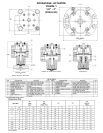
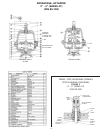
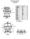
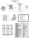
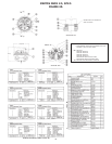
Consult factory for details, see Figure 7.
3.8.2.1 Remove cover bolts and lift off top
cover.
3.8.2.2 Caution: actuator plates are under
load. Loosen the indicator spindle two
turns before placing centrally in the fix-
ture, locating the compressor over the
correct spacer in the fixture lower
plate. Place the slotted fixture plate
and spacer plate on the actuator top
plate; turn the fixture handwheel
clockwise to remove the load from the
indicator spindle. Remove the spindle
and turn the handwheel counterclock-
wise until the spring load is relieved.
Use care - the diaphragm may pinch
the spindle thread and restrict spring
extension. Examine the diaphragm
through hole for damage and replace,
if necessary.
3.8.2.3 Place the spring in the lower cover and
set an actuator plate, concave side
down, over the valve spindle. Position
in the fixture over the spacer and place
the slotted fixture plate on the actua-
tor plate. Set the spacer plate on top,
turn the fixture handwheel clockwise
and compress the spring until the actu-
ator plate shoulders on the spindle.
Use care to insure the spindle goes
through the actuator plate center hole.
Slide the actuator diaphragm over the
valve spindle using care to insure the
top hat is in the upper cover. Position
the actuator diaphragm so the bolt
clearance holes line up with thread-
ed inserts in lower cover. Place an
actuator plate, concave side up, over
the valve spindle. Apply Blue Loctite
#242 and thread the indicating spindle
on the valve spindle by hand. Turn the
handwheel counterclockwise to
remove the load and remove the actu-
ator from the fixture. Clamp the slot-
ted plate in a vise and pull so the actu-
ator slips free. Tighten the indicator
spindle with a wrench using care to
insure the actuator diaphragm remains
properly aligned.
3.8.2.4 Position the upper actuator cover so
the 1/8” NPT inlets in the upper and
lower covers are in line.
3.8.3 Actuator Diaphragm or Spring Replacement:
(3” & 4” Series 47, DIN 80 & 100) If present,
switch package must be removed.
3.8.3.1Disconnect air lines. It is best to
remove the bonnet bolts, lift actuator
assembly from the valve body and
move the unit to a bench.
3.8.3.2 Remove clear plastic cap, travel stop
nuts and roller bearing/races.
3.8.3.3 Remove actuator bolts and nuts, lift off
top cover.
3.8.3.4 Remove adjusting bushing, spindle nut
(under load due to spring force),
diaphragm plates, actuator diaphragm
and spring.
3.8.3.5 Using replacement parts, reverse
instructions for reassembly. Use Blue
Loctite #242 on the spindle nut. Be
sure to set the adjusting bushing at
the correct location (4.06” (10.31 cm)
from top of the spindle nut to bottom
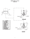
of adjusting bushing), see Figure 1.
(3” & 4” Series 33, DIN 80 & 100)
3.8.3.6Disconnect air lines. It is best to
remove bonnet bolts, lift actuator
assembly from the valve body and
move the unit to a bench. Remove
actuator bolts an remove top cover.
3.8.3.7 Remove extension spindle, both nuts,
diaphragm top plate, actuator
diaphragm and spring.
3.8.3.8 Reassembly is the reverse of the above,


