15
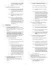
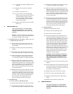
7.2.1Remove top switch package cover.
7.2.2Place valve in full open position.
7.2.3Connect test device to terminal strip for open
switch. The switch type, inductive proximity
versus dry contact mechanical, determines the
type of test device required. Contact switches
use a traditional volt meter with resistance
capability to verify continuity, inductive proxim-
ity switches cannot use this method. Proximity
switches require an inductive proximity tester,
such as Pepperl+Fuch’s model #1-1350, which
supplies the proper load and supply voltage to
the switch. Inductive proximity switches must
be energized with the correct load and supply
voltage to sense the target.
WARNING: DO NOT SHORT THE INDUCTIVE
PROXIMITY SWITCH BY DIRECTLY CONNECT-
ING A POWER SUPPLY, IRREPARABLE AND
IMMEDIATE DAMAGE CAN OCCUR TO THE
SWITCH.
7.2.4 Bio-1.50” (Two Switch Actuators)
7.2.4.1 Verify the switch package locking set
screw is tight.
7.2.4.2 Verify the circuit board is firmly seat-
ed.
7.2.4.3 For mechanical switches only, press on
the top of the circuit board to move it
toward the switch actuator. Thread the
switch actuator two (2) turns past the
initial switch indication.
7.2.4.4 Lock in place with the set screw on
switch actuator.
7.2.5 2.0” (One switch actuator)
7.2.5.1 Do not set the switch in the open
position, set the switch in closed posi-
tion. Follow 7.2.4 with the valve in full
closed position. Confirm open switch
functions in full open position only
after setting in closed position.
7.2.6Place the valve in the full closed position and
connect the appropriate test device to the ter-
minal strip for valve CLOSE switch. Repeat sec-
tion 7.2.4-7.2.5 for the valve CLOSED switch.
Note on SP 3.0 units, the closed switch actua-
tor must never hit the adapter in the closed
position with body attached.
8 POSITIONERS
(Switches and Positioners cannot be used
together)
(A special adjusting bushing is required for 3”
& 4“ (DIN 80 & 100) Actuators with position-
ers)
8.1 Scope: Top-mounted positioners listed below
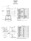
8.1.1 Moore 73N12F (A100 & A300 Series Actuators)
(Direct Acting Positioner, Top Loading)
8.1.2 Moore 73NB (A200 Series Actuators) (Direct
Acting Positioner, Bottom Loading)
8.1.3 Moore 73NFR (A100 & A300 Series Actuators)
(Reverse Acting Positioner, Top Loading)
8.2 Supply and Instrument Pressures
8.2.1Instrument input pressure range - as specified:
3-15 psi (.21 - 1.03 bar) (standard), 3-9 psi
(.21-.62 bar), 6-30 psi (.41-2.07 bar) and others
are optional.
8.2.2Supply pressure: 3 psi (.21 bar) above required
actuator pressure to a maximum of 90 psi (6.2
bar). A filtered air supply is recommended.
8.2.3Caution: Pressure in excess of 90 psi (6.2
bar) to any connection may cause damage.
8.3 Description
The positioner is designed to operate a valve actua-
tor to maintain the valve in a position determined by
the control instrument. The above positioners are
direct acting - with an increase in instrument pres-
sure, the pressure to the actuator (positioner output)
will increase or reverse acting - with an increase in
instrument pressure, the pressure to the actuator
(positioner output) will decrease. On a bottom load-
ing positioner (73NB), output is connected to the
actuator lower chamber via an external tube.
Therefore, the valve will open as instrument pressure
increases. The 73NB is the only unit which can have
an O-ring in the actuator upper cover
. All others
operate on the concept that air feeds the upper
cover by flowing down the indicating shaft and into
the cover. (This means that a field retrofit for
Double and Direct units must have the O-ring
removed and a special slotted adjusting bushing.)
Double Acting (A300 Series) require the lower actua-
tor cover to be pre-loaded, use a bleed off type regu-
lator with gauge. (This is standard when ITT supplies
the assembly.)
8.4 Installation
The only task is to connect the supply and instru-
ment air. All connections are 1/4” NPT. Use 1/4” O.D.
tubing for the instrument connection, either 1/4” or
3/8” O.D. (6.35 or 9.52 mm) tubing for the supply
connection. Blow out all piping before connections
are made to prevent the possibility of dirt or chips
entering the positioner. Use pipe sealant sparingly,
and then only on the male threads. A non-hardening
sealant is strongly recommended. Connect the posi-
tioner to a source of clean, dry oil-free air. A filtered
and regulated air source is recommended.
Note: Synthetic compressor lubricants in the air
stream at the instrument may cause the position-
er to fail.
Note that a cushion loading regulator is furnished
with 3300 series actuators and a tee in the supply
connection is routed to this regulator, so an extra
hookup is not required. The cushion loading regula-
tor should be set at the minimum pressure required
to open the valve wide open. Typically, this is 10 psi
(0.69 bar) or less.


