


11
4.3.1.1 If present, the switch package must be
removed.
4.3.1.2 Release any air pressure in bottom
cover.
4.3.1.3 Remove clear plastic cap.
4.3.1.4 Use a wrench to turn the adjusting
bushing counter clockwise to close the
valve (record the number of turns).
Turn the adjusting bushing clockwise
the same number of turns to return
valve to open position.
4.3.1.5 Tighten Travel Stop nuts and assemble
plastic cap.
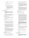
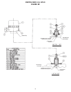
5 SWITCH PACK 2.0
(The switch package is not autoclavable,
maximum temperature is 150˚ F 65.5˚C)
(Switches and Positioners cannot be used
together)
Retrofit - The switch package as received from
the factory is pre-set, only minimal adjustment
is required to adapt to the actuator.
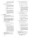
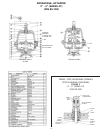
5.1 Field Mounting (1/4” through 2”, DIN 8 - 50, 3” &
4”, DIN 80 & 100, Series 33)
5.1.1Remove the four(4) stainless steel screws on
the actuator top cover. Place the valve in the
open position.
5.1.2Remove the plastic plug from the indicating
spindle.
5.1.3Thread the switch indicating spindle into the
valve indicating spindle. Use Blue Loctite #242.
5.1.4Mount the adapter, insure that both O-Rings
are on the adapter and lubricated with Dow
111. The correct torque is 5 in-lbs (.656 Joules).
5.1.5Slide the switch sub assembly down over the
adapter, position the conduit entrances in the
location most desirable, (45˚ increments), press
down and tighten the set screw located on the
side of the lower housing to lock the unit in
place. The set screw torque should not exceed
5 in-lbs (.656 Joules).
5.1.6Holding the lower housing stationary, unscrew
the top switch package cover and wire to the
terminal strip (Reference factory wiring decal).
Verify the switches operate correctly by cycling
the valve, see 5.3 for switch adjusting proce-
dure. Screw the switch package cover on,
insure the O-Ring remains in the groove.
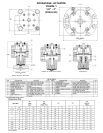
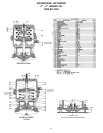
5.2 Field Mounting
(3” and 4” Series 47, DIN 80 and 100)
5.2.1Remove the clear plastic cap from the actuator.
5.2.2Thread the switch indicating spindle into the
valve indicating spindle. Use Blue Loctite #242.
5.2.3Thread on the adapter, insure that the O-Ring
is in place at the base of the adapter.
5.2.4Slide the switch sub assembly down over the
adapter, position the conduit entrances in the
location most desirable, (45˚ increments), press
down and tighten the set screw located on the
side of the lower housing to lock the unit in
place. The set screw torque should not exceed
5 in-lbs (.656 Joules).
5.2.5Holding the lower housing stationary unscrew
the top switch package cover and wire to the
terminal strip (Reference factory wiring decal).
Verify the switches operate correctly by cycling
the valve, see 5.3 for switch adjusting proce-
dure. Screw the switch package cover on,
insure the O-Ring remains in the groove.
5.3 Setting Switches
(Switches are identified with decal)
5.3.1Remove top switch package cover.
5.3.2Place valve in full open position.
5.3.3Connect test device to terminal strip on con-
nections identified for SW (open) switch. The
switch type, inductive proximity versus dry con-
tact mechanical, determines the type of test
device required. Contact switches use a tradi-
tional volt meter with resistance capability to
verify continuity, inductive proximity switches
cannot use this method. Proximity switches
require an inductive proximity tester, such as
Pepperl+Fuch’s model #1-1305, which supplies
the proper load and supply voltage to the
switch. Inductive proximity switches must be
energized with the correct load and supply
voltage to sense the target.
WARNING: DO NOT SHORT THE INDUCTIVE
PROXIMITY SWITCH BY DIRECTLY CONNECT-
ING A POWER SUPPLY, IRREPARABLE AND
IMMEDIATE DAMAGE CAN OCCUR TO THE
SWITCH.
5.3.4Loosen the two (2) screws on the open switch
slightly.
5.3.5Use the adjusting screw accessible from the top
to move the switch up or down the bracket to
the optimum position. (Two turns past the trig-
ger location is recommended.)
5.3.6Tighten the two (2) screws on the switch.
5.3.7Place the valve in the full closed position.
5.3.8Repeat the above steps for the SW (closed)
switch.
5.3.9Replace the top switch package cover.
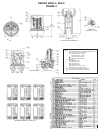
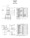
6 SWITCH PACK 2.5
(The switch package is not autoclavable,
maximum temperature is 150˚F, 65.5˚C)
(Switches and Positioners cannot be used
together)