


13
© 2002 directed electronics, inc.
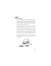
If the vehicle requires more than one ignition as per the Web site
information follow the same test procedure and solder the thick
PINK/WHITE wire to it and be sure to cover your connection
with electrical tape. If your vehicle requires more than two igni-
tions, contact Hornet Technical Support.
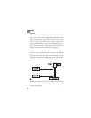
step 3
Accessory and Starter wires
The starter and accessory wires will be located in the same harness
as the ignition and constant power. Leaving the meter black lead
connected to the metal ground, take the red lead and probe the
wire suspected to be the accessory. With the key off, your meter
should read 0.00 volts. Turn the key to the on position and the
meter should read between 11.00 volts and 13.00 volts. Now
turn the key to the crank position. If you have the correct wire
the voltage will disappear while the starter is cranking and return
once the key returns to the on position. If the wire tests correctly,
solder the thick ORANGE wire off the relay satellite pack and
secure it with electrical tape. If your vehicle requires more than
one accessory contact Hornet Technical Support.
➜