


12
© 2002 directed electronics, inc.
Once the constant power wire has been identified, solder the two
thick RED wires from the relay satellite pack to it and cover the
connection with electrical tape to ensure a safe connection.
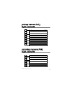
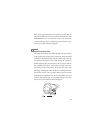
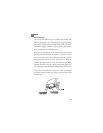
With the meter black lead still in the kick panel, locate the igni-
tion wire harness in the same location. It will test differently than
constant (+)12 volts. Locate the suspected wire using the
www.diyhornet.com Web site and place the red lead of the meter
on the suspected wire. With the key in the off position the meter
will read 0.00 volts. Turn the key to the on position and the meter
should read between 11.00 volts and 13.00 volts. Now watching
the meter, turn the key to the crank position and the voltage
should drop a small amount but not disappear. If the voltage
disappears this is not an ignition wire but an accessory wire. If the
wire meters correctly, solder the thick PINK wire of the relay
satellite pack to it and cover the connection with electrical tape.
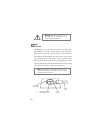
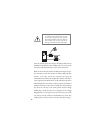
warning! Before making any connection
to constant battery power make sure that
the two green 30 amp fuses are removed
from the fuse holders on the two thick red
wires. Failure to do so may cause fire or
shorting of sensitive electrical components.