


CLASS 500 ADVANCED KWH/DEMAND METER
62-0304—05 6
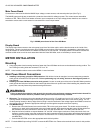
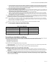
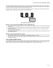
Fig. 3. Split core current sensor assembly.
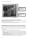
Fig. 4. Split core current sensor assembly installed.
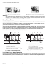
IMPORTANT:
When looking from the source side of the conductor(s) being monitored, you should see the arrow on the current sensor
assembly. The arrow should be pointing in a clockwise direction around the conductor(s) being monitored. If the arrow is
not positioned on the source side, the resulting readings will be inaccurate.
Current Sensor Wiring
Once all the current sensors are installed onto their appropriate phase conductors, you can begin terminating the current sensors
onto the Class 500 Meter main board.
The current sensor leads can be extended up to 500 feet for remote monitoring applications. To extend the length of the wires,
use #22 AWG twisted pair wire with a black and white conductor, rated for 600 VAC.
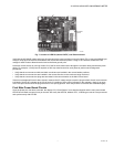
The current sensor connection points are located on the bottom center of the main power board. Three removable plugs exist,
one for each current sensor phase input. The header portions of the connectors are labeled TB2, TB3, and TB4. The silkscreen
located in front of each connector instructs you which terminal of the plug is for the white conductor and which terminal is wired to
the black conductor. Once each current sensor is wired to its respective plug, insert each plug into the appropriate header.
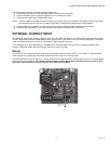
MAINS LINE VOLTAGE AND CURRENT SENSOR WIRING DIAGRAMS
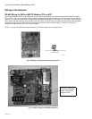
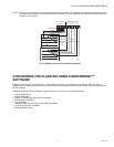
Fig. 5. 3-phase, 4-wire installation diagram.
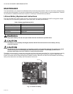
Fig. 6. 3-phase, 3-wire installation diagram.
Line Voltage/Current Sensor Diagnostics
Ensure that the three-phase AC MAINS voltage wiring and the current are connected in the proper phase sequence. If there is a
phase sequence error, the display LCD will show the message “Check Sensor” in the upper right hand corner. Additionally, LED
D5 labeled “MTR” (See Fig. 7) will flash at a rate of twice per second in the event of a phase error or missing phase voltage(s).
B W
N
LINE VOLTAGE
ØA
ØC
LOAD SOURCE
ØB
B W
M32788
ØA
ØA ØB ØC
ØB
B W
CURRENT SENSORS
ØC
N
NOTES: LINE VOLTAGE CONNECTIONS: 14-22 AWG
SENSOR CONNECTIONS: B=BLACK LEAD, W=WHITE LEAD
1/10A, 600 VAC INLINE FUSE PER CONDUCTOR.
LITTLEFUSE PART NUMBER KLDR 100.
NEUTRAL NOT USED IN DELTA SYSTEM. REMOVE NEUTRAL
TERMINAL BLOCK SCREW FOR DELTA SYSTEMS.
B W
N
LINE VOLTAGE
Ø
A
ØC
LOAD SOURCE
ØB
B W
M32797
ØA
ØA ØB ØC
ØB
B W
CURRENT SENSORS
ØC
NOTES: LINE VOLTAGE CONNECTIONS: 14-22 AWG
SENSOR CONNECTIONS: B=BLACK LEAD, W=WHITE LEAD
1/10A, 600 VAC INLINE FUSE PER CONDUCTOR.
LITTLEFUSE PART NUMBER KLDR 100.
NEUTRAL NOT USED IN DELTA SYSTEM. REMOVE NEUTRAL
TERMINAL BLOCK SCREW FOR DELTA SYSTEMS.