CLASS 500 ADVANCED KWH/DEMAND METER
13 62-0304—05
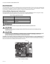
Use the following procedure to replace the lithium battery cell.
1. Disconnect power from the Class 500 Meter at the unit external circuit breaker.
2. Remove the battery from its socket and place it on a non-conductive surface.
3. Install the new battery into the PCB battery socket.
NOTE: The main power board battery socket is keyed to prevent the user from inserting the new battery in the wrong polarity.
No damage will occur to the unit or battery if the battery is inadvertently installed in the wrong direction.
4. Visually inspect the new battery to verify that all leads are fully inserted into their respective socket positions.
5. Dispose of the used battery in accordance with the manufacturer’s (Eagle Picher) instructions.
EXTERNAL CONTACT INPUT
Two additional channels are available (channels 3 and 4) on the Class 500 Meter to be used for capturing pulses from external
devices. These devices can be another electric meter, a water meter, a gas meter, or any unit with an output pulse. The output
pulse of the device must be in the form of a dry contact - either physical or electronic.
Count speeds of up to 10 Hz (600 ppm) are accepted by the Class 500 Meter, and the count is available at Modbus point
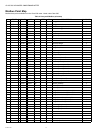
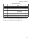
locations 41083 and 41085. See the point-map (Table 4) for more information.
Wiring
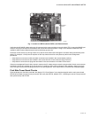
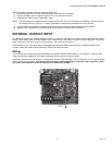
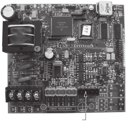
The external pulse is wired into the Class 500 Meter through the terminals marked “INPUT 1” and “INPUT 2” (TB6 and TB7).
These consist of removable plug and header assemblies similar to the current sensor inputs.
The external device can be mounted up to 100 feet away from the Class 500 Meter, and wire sizes from 24 to 16 gauge (AWG)
can be used for the connection. If the external device utilizes a polarity-dependent, solid-state contact, the plus (+) from
the contact must terminate on the left hand pin of the headers on the Meter.
INPUT 1 and
INPUT 2
M29701


