


CLASS 500 ADVANCED KWH/DEMAND METER
62-0304—05 10
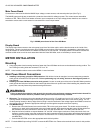
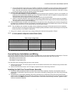
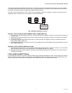
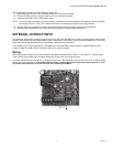
Fig. 11. LON wiring.
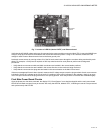
Ethernet wiring for BACnet IP, and Modbus TCP/IP and Ethernet EZ-7
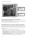
These models are shipped with a board that allows for Ethernet communication via Modbus TCP/IP, BACnet IP or Ethernet EZ-7.
EZ-7 protocol is required when using the Energy Software.
Modbus TCP/IP and BACnet IP, and Ethernet EZ-7 connections are made to the RJ45 connection on the Ethernet board (Fig. 7
on page 7). No RS-485 daisy-chain capabilities exist with with these Ethernet connections.
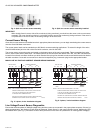
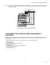
MONITORING MULTIPLE LOADS WITH ONE CLASS 500 METER
The Class 500 Meter provides extreme flexibility by allowing additional sets of current sensors to be used in parallel so multiple
load locations can be monitored by one Class 500 Meter. This feature allows a totalized display readout of two or more load
circuits.
You may use parallel sensors to monitor specific breakers from one panel, specific breakers from more than one panel, two or
more complete panels, etc.
When paralleling current sensors, the following rules must be followed for accurate readings:
1. Current sensors must be installed in complete sets of three, with a maximum of three sensors installed in parallel per
phase.
2. All sensors used in parallel must be of the same amperage rating (i.e. 100 Amp, 200 Amp, etc.). The rating is determined
by the current rating (amperage) of the Class 500 Meter. For example, a 200 Amp Class 500 Meter must use extra sets of
200 Amp current sensors.
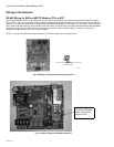
3. All locations being monitored must have the same power source. A 480 volt Class 500 Meter, for example, cannot monitor
a 208 volt load circuit nor can a Class 500 Meter monitor two 480 or 208 volt loads if they are from different originating
power sources or from different transformers.
4. The display readings must be multiplied by the number of sets of current sensors installed. For example, for Class 500
Meter reading of 5 KWH with 2 sets of currents sensors you will have 5 x 2 = 10 KWH (actual usage).
SERVICE PIN SWITCH (BLUE
PUSH BUTTON):
BROADCASTS LON NEURON
ID TO LON NETWORK.
ASSISTS IN SETUP OF
DEVICE ON LON NETWORK.
LONWORKS MODULE. NOTE
2 POSITION TERMINAL
BLOCK FOR TWISTED PAIR
CONNECTION