


62-86-25-14
Quick Start Guide for Herculine 2000 Series Actuators
February 2007
Page 5 of 10
Considerations
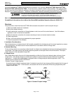
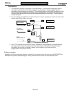
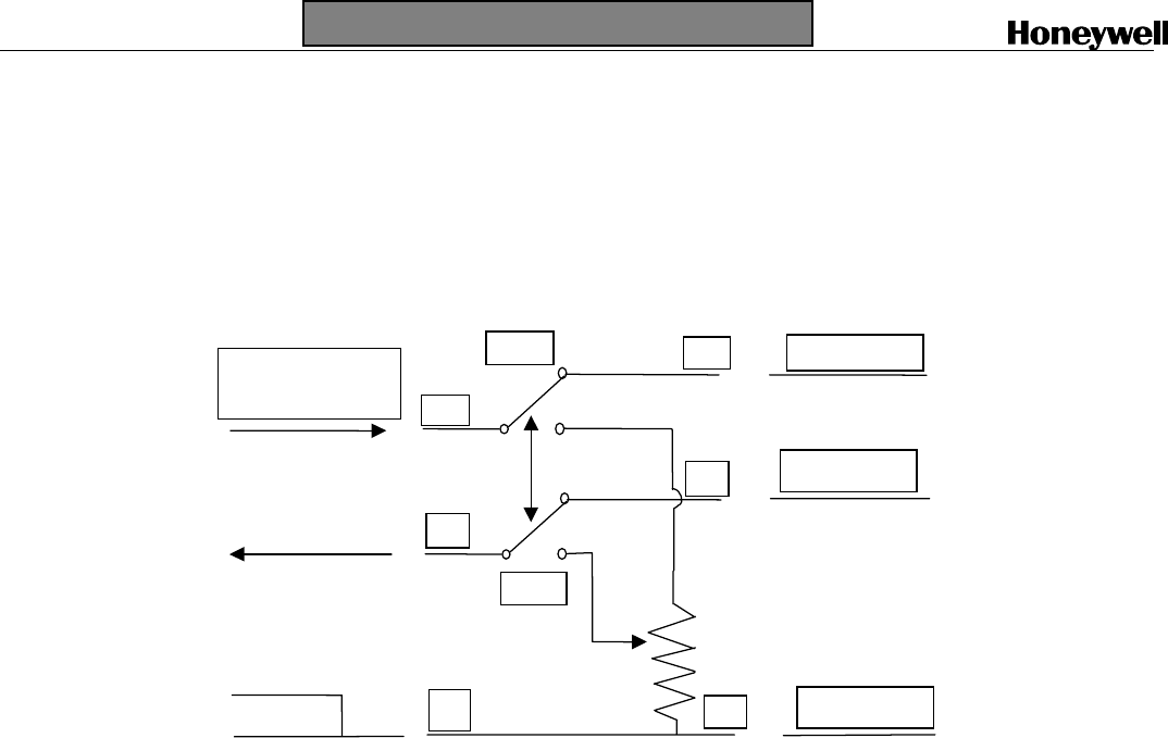
1. This connection performs an emulation of a series 90 motor. If the controller being used is also an
emulation of a Series 90, the connections required may be different. Shown in Figure 7are the
connections found necessary to connect a T775 controller through an S443A S90 Auto/Manual Control.
If the controller has the capability to provide a 4/20 or voltage output, it is easier to use that mode. It
will require only two wires and it will allow the independent use of the 4/20 output. If help is required,
contact Honeywell.
2. Due to variations in the definition of rotation directions, it may be necessary to reverse the action of the
actuator from CCW to CW or vice versa.
GND to
HercuLine2001 (2)
W
W
W
R
R
B
B
A
uto
Man
I out from
HercuLine2001
+ Signal to
HercuLine2001
T775 B 3
T775 W 1
T775 R 2
Figure 7 T775 Controller connections
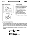
3. In the T775 controller manual there are several examples of using resistances or potentiometers as
high and low limit controls. Because of the mode of emulation of Series 90, it is likely that these
connections will not work as intended. Instead, use the output or input limits which are
programmable in the HercuLine
®
2001.
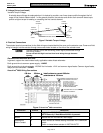
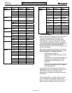
5. Power up actuator.
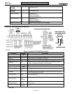
Depending on which power supply selection is ordered for your actuator, wire the power input (MAIN POWER) as
described in the previous tables and figures. Wiring must conform to national and local electrical codes.