62-86-25-14
Quick Start Guide for Herculine 2000 Series Actuators
February 2007
Page 1 of 10
Honeywell’s HercuLine
®
2000 series actuators are available in four versions: HercuLine
®
2000, HercuLine
®
2001,
HercuLine
®
2002, and HercuLine
®
2003. All are low torque, precision electric rotary actuators. This guide provides
you with mechanical and electrical installation information required to mount and connect the HercuLine
®
2000 Series
Actuator to your specific application. Installation considerations, electrical and safety precautions should be observed.
An external disconnect switch must be installed to break all current carrying
conductors connected to the actuator. Turn off power before working on
conductors. Failure to observe this precaution may result in serious personal injury.
Refer to the Model Selection Guide on Pages 9 and 10 to determine which features and functions are on your model.
For additional information, refer to HercuLine Series 2000 Installation/Operation Manual # 62-86-25-10
Overview
The procedures to install the HercuLine
®
2000 Series actuator and place it in service require that you:
1. Select a suitable location for installation.
2. Mount the actuator securely.
3. Install mechanical connections or linkage between control arm and final control element. Use HAL software
application to aid in mechanical installation.
4. Make all electrical connections for actuator according to local and national electrical codes.
5. Power up actuator.
6. Enter, verify and adjust set up parameters for proper operation.
7. Check the operation of the Actuator
1. Installation Considerations
Mount the actuator in a location where it will be easily accessible for maintenance and for manual operation by means
of the hand wheel. The exact location must be determined in accordance with the linkage used.
2. Actuator Mounting
Firmly bolt the actuator to a mounting surface that will not distort when subjected to the torque stresses generated by
the actuator. The output shaft of the actuator should be parallel to the output shaft of the driven device. The output
shaft crank arm is fully adjustable through 360°.
3. Linkage Set-up
Many applications require the use of a linkage assembly and often the final control element does not have a linear
torque curve. The actuator linkage can be set up to achieve an optimal delivered torque distribution for specific
applications. To assist with linkage design, Honeywell offers a linkage analysis software application (HAL). The
software can be ordered as P/N 51197910-001.
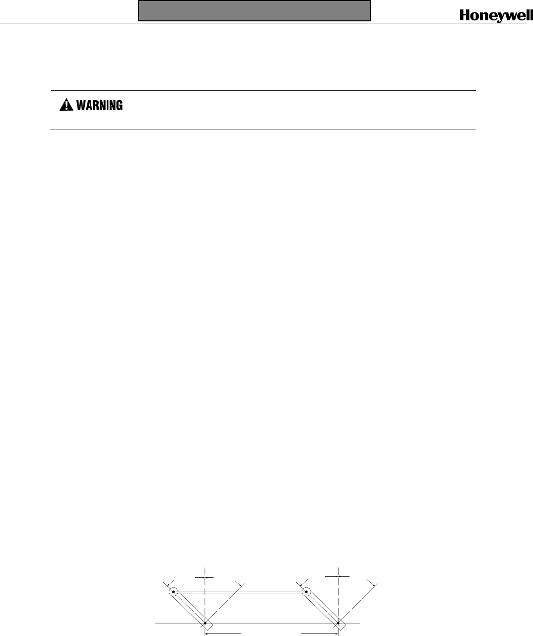
Constant Torque Linkage (typical)
A constant torque linkage is employed when it is desired to provide a linear torque profile throughout the full range of
final control element travel. In this situation, the actuator and driven crank arms will be set-up proportionally with
respect to each other.
Vertical
Centerline
45° 45°
Vertical
Centerline
45° 45°
Start Stop Close Open
Drive Unit
Crank Arm
Damper
Crank Arm
Linkage
Horizontal Offset
a/n 23199
Figure 1 Constant Torque Linkage


