IR‐1001_OMN_1‐09
4
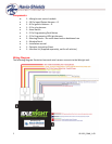
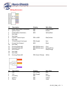
VehicleInstallationJ1,16‐PinHarness:
1. Green/White‐‐Brakeinput(+)–Usedforbothprogrammingmodeandremotesafety
shutdown.Connecttobrakelightswitchwhenbrakeispressed.
2. Yellow‐‐Ignitioninput(+)–Connecttoignitionswitchwirepoweredby12vwhen
ignitionisonandcranking.
3. White/Black–Hood(‐)–Safetypin‐switch
4. NOTUSED
5. NOTUSED
6. Blue/Yellow–Lightbartriggerinput(‐)or(+)
7. NOTUSED
8. Red–Connecttobatteryconstant12v(with20Afuseholder)
9. Black–Connecttogoodchassisground
10. NOTUSED
11. Gray–Runningoutput#1(‐).Groundedoutputwhenremotestartisrunning.(200mA
max.)
12. Brown/White–Runningoutput#2(‐).Groundedoutputwhenremotestartisrunning.
(200mAmax.)
13. Blue/Orange–RFIDcontrollineoutput(‐).ConnecttoexternalRFIDbypassmodule
controlline
14. NOTUSED
15. NOTUSED
16. NOTUSED
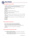
VehicleInstallationJ2,6‐PinHarness:
1. Red–Connecttoconstant12vsource(mustbecapableof25A)
2. Red–Connecttoconstant12vsource(mustbecapableof25A)
3. Orange–ConnecttoignitionswitchACCcircuit(AirCond/Heater,etc.)
4. Yellow–Connecttoignitionswitchwirepoweredby12vwhen
ignitionisonand
cranking.
5. Violet–Connecttostarterwirepoweredonlyoncrankingposition.
6. NOTUSED
VehicleInstallation,3‐PinRelayHarness,White:
1. Connecttoexternalrelaypackifnecessary.
a. Relay#1‐‐Purplewireto12Vfused25Asource,BluewiretoACC,Ignitionor
Starter(dependingonprogrammode)
b. Relay#2‐‐Purplewireto12Vfused25Asource,GreenwiretoACC,Ignitionor
Starter(dependingonprogrammode)


