Service
306674V 11
Reassembly
1. Clean all the parts carefully in a compatible solvent
and inspect for wear or damage. Use all the repair
kit parts during reassembly and replace other parts
as necessary.
2. Check the polished surfaces of the piston, piston rod
and cylinder wall for scratches or wear. A scored rod
will cause premature packing wear and leaking.
3. Lubricate all parts with a light, waterproof grease.
4. Be sure the o-rings are in place. Slide the piston rod
down through the throat bearing and lower the pis-
ton (5) into the air motor base (56).
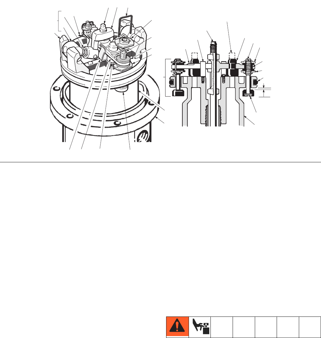
5. Pull the exhaust valve poppets (38) into the valve
actuator (13) and clip off the top part shown with
dotted lines. (F
IG. 5)
6. Install the transfer valve poppets (37) onto the valve
stems (30), then reassemble the valve stems (30),
bottom adjusting nuts (27), grommets (18), and top
adjusting nuts (27) on the piston (5). Assemble the
trip rod (1), valve actuator (13), trip rod yoke (14)
and toggle assemblies (K) on the piston. (F
IG. 5)
7. Before installing the lockwires (28) in the adjusting
nuts (27), use the special gauge, 171818, to adjust
the transfer valve (M) so there is 0.125 in (3.68 mm)
clearance between the poppets (37) and the piston
(5) when the toggle assemblies are in the down
position. (F
IG. 5)
8. Snap the toggle assemblies (K) to the up position.
Reinstall the cylinder (32) and cap nut (31). Reas-
semble the air motor to the displacement pump.
9. Before remounting the pump, connect an air hose
and run the pump slowly, at about 40 psi (0.28 MPa,
2.8 bar) to ensure that it operates smoothly.
10. Reconnect the ground wire before regular operation.
Throat Packing
See FIG. 6 and the parts drawing and list on pages 14
and 15 for further information.
1. Clamp the pump in a vise and unscrew the riser
tube (80) from the air motor base (56). Pull the riser
tube away from the air motor until the cotter pin (60)
which secures the displacement pump connecting
rod to the air motor piston rod (52) is visible.
FIG. 5
K
Push toggles (K) in
and then up.
Turn wires up.
L
114
28*
27*
30*
18*
5
56
17
16
4 38*13
27*
37*
Cut off tops of
poppets (x) as
indicated by dotted
lines
0.125 in.
(3.18 mm)
CUTAWAY VIEW
1
4
13
38*
30*
27*
18*
27*
20*
5
37*
M


