


Page A-2 GDU 37X Installation Manual – Pinouts
Revision B 190-01054-01
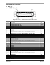
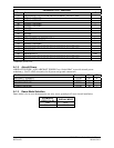
Connector P3701, continued
Pin Pin Name I/O
33 RESERVED FOR FUTURE DEVELOPMENT, DO NOT USE --
34 SIGNAL GROUND --
35 SIGNAL GROUND --
36 SIGNAL GROUND --
37 SIGNAL GROUND --
38 SPARE --
39 SPARE --
40 SPARE --
41 SPARE --
42 CDU SYSTEM ID PROGRAM* 4 In
43 14V LIGHTING BUS HI In
44 SIGNAL GROUND --
45 RESERVED FOR FUTURE DEVELOPMENT, DO NOT USE --
46 RESERVED FOR FUTURE DEVELOPMENT, DO NOT USE --
47 RS-232 IN 1 In
48 RS-232 OUT 1 Out
49 RESERVED FOR FUTURE DEVELOPMENT, DO NOT USE --
50 RESERVED FOR FUTURE DEVELOPMENT, DO NOT USE --
* Indicates Active Low
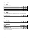
A.1.2 Aircraft Power
AIRCRAFT POWER 1 AND AIRCRAFT POWER 2 are “diode ORed” to provide aircraft power
redundancy. Use 22 AWG wire (min) for all power and ground connections.
Pin Name Connector Pin I/O
AIRCRAFT POWER 1 P3701 32 In
AIRCRAFT POWER 2 P3701 31 In
POWER GROUND P3701 15 --
POWER GROUND P3701 16 --
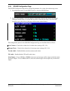
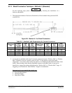
A.1.3 Demo Mode Selection
Demo mode is for in-store demonstration use only, never ground pin 42 in an aircraft installation.
PFD MODE 4
(P3701, Pin 42)
DISPLAY MODE
Open MFD
Ground DEMO