


GDU 37X Installation Manual – Installation Overview Page 1-3
190-01054-01 Revision B
1.4.4 Cooling Requirements
While no forced cooling air is required for the GDU 37X, it is highly recommended that the air behind the
panel be kept moving (by ventilation or a fan).
NOTE
Avoid installing the GDU 37X LRUs near heat sources. If this is not
possible, ensure that additional cooling is provided. Allow adequate
space for installation of cables and connectors. The installer will supply
and fabricate all of the cables. All wiring should be in accordance with
FAA AC 43.13-1B and AC 43.13-2A.
1.5 Mounting
Refer to Sections 2 and 3 for specific mounting instructions for each component of the GDU 37X, and to
Appendix C for Outline & Installation Drawings.
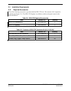
1.6 Wiring/Cabling Considerations
Use MIL-W-22759/16 (or other approved wire) AWG #24 or larger wire for all connections unless
otherwise specified. The standard pin contacts supplied in the connector kit are compatible with up to
AWG #22 wire. In cases where some installations have more than one LRU sharing a common circuit
breaker, sizing and wire gauge is based on aircraft circuit breaker layout, length of wiring, current draw
on units, and internal unit protection characteristics. Do not attempt to combine more than one unit on the
same circuit breaker.
RG400 or RG142 coaxial cable with 50 Ω nominal impedance and meeting applicable aviation
regulations should be used for the installation.
1.6.1 Wiring Harness Installation
Allow adequate space for installation of cables and connectors. Ensure that routing of the wiring does not
come in contact with sources of heat, RF or EMI interference. Analog Input wires routed too close to
spark plugs, plug wires, or magnetos may result in erratic readings.
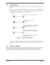
The installer shall supply and fabricate all of the cables. The connector is available in the GDU 37X
Connector Kit (011-01921-00). Electrical connections are made through D subminiature connectors for
the GDU 37X units. Appendix A defines the electrical characteristics of all input and output signals.
Required connectors and associated hardware are supplied with the connector kit.
CAUTION
Check wiring connections for errors before connecting any wiring
harnesses. Incorrect wiring could cause internal component damage.