


5GPSMAP 4000/5000 Series Installation Instructions
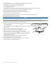
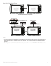
6. Placethechartplotterinthehole,andmakesurethatthemountingholesonthechartplotterlineupwiththepilotholesontheush-mount
templateaftercutting,sanding,andlingthehole.Iftheydonot,markthelocationswherethepilotholesneedtobe.
7. Usingthecenterpunch,indentthecenterofeachofthemounting-holelocations.
8. Usingthe
3
/
8
inchdrillbit,drillthemountingholes.
NOTE: If you are mounting the chartplotter in berglass, it is recommended to use a countersink bit to drill a clearance-counterbore through only the top
gel-coat layer. This will help to avoid any cracking in the gel-coat layer when the screws are tightened.
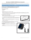
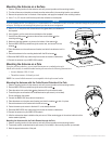
9. Installtherubbergasketonthebackofthechartplotter.Thetopandbottomsectionswilllineupwiththeholes.Thesidesectionswilllineup
withthenotchesinthecaseforthesuncover.
NOTE: To prevent corrosion of the metal contacts, cover unused connectors (page 20) with the attached weather caps.
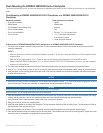
10.Placethechartplotterintothecutout.
11.Securelytightentheincludedmountingscrewsthroughthechartplotterintothepilotholes.
NOTE: Stainless-steel screws may bind when screwed into berglass and overtightened. Garmin recommends applying an anti-galling, stainless anti-
seize lubricant to the screw before using.
12.Replacethemountingcoversbysnappingthemintoplace.
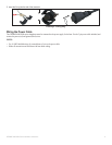
notice
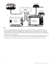
Be sure to follow the correct mounting directions and the correct wiring directions for the antenna included with your chartplotter.
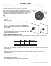
You can surface mount the antenna, attach it to a standard marine pole mount, or install the antenna under berglass.
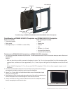
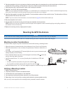
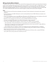
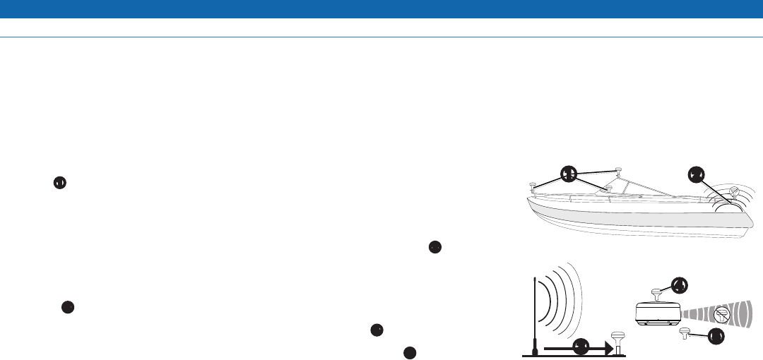
To ensure the best reception, keep these considerations in mind while selecting a mounting location.
• Mount the antenna in a location that has a clear, unobstructed view of the sky in all directions.
• Mount the antenna where it is not covered by the superstructure of the boat, a radar device, or
a mast
➊
.
• On a sailboat, avoid mounting the GPS antenna high on the mast to prevent inaccurate speed
readings caused by excessive heeling.
• Do not install the antenna near sources of electromagnetic interference (EMI)
➋
, such as the
motor or other large marine electronics.
• Install the antenna at least 3 ft. (1 m) away from the path of a radar beam or VHF radio
antenna
➌
.
• It is best to install the antenna above the path of the radar beam
➍
.
• It is acceptable to install the antenna under the path of the radar beam
➎
.
• Install the antenna at least 2 in. (5 cm) from a magnetic compass to avoid interfering with the compass.
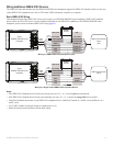
1. Selectamountinglocation.
2. Temporarilysecuretheantennaintheselectedlocation.
3. Testtheantennaforcorrectoperationonthechartplotter.
4. Ifyouexperienceinterferencewithotherelectronics,tryadifferentlocation.
5. Repeatsteps3and4untilyoundamountinglocationwheretheantennaoperatescorrectly.
After you verify correct operation at the mounting location, permanently mount the antenna.
➎
➍
➌
➊
➋