


8 GMR 600/1200 Series Installation Instructions
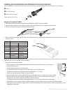
Installing the Field-Installable RJ-45 Network Connector (Optional)
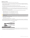
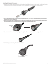
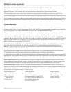
A eld-installable RJ-45 network connector is provided for you to create a network cable that is the correct length for your installation.
➊
O-Ring
➋
RJ-45 modular plug
➌
Ethernet cable termination
Copper tape strip (not shown)
➊
➋
➌
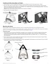
Preparing the Network Cable
1. Cleanly cut your Ethernet cable to the desired length. Retain the cut RJ-45 connector for Step 4.
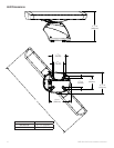
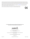
2. Remove the strain-relief nut from the cable-connection housing and slide it onto the cut end of the cable as shown.
3. Feed the cut cable end through the connection housing as shown.
Strain relief
Cut end of cable
Connection
housing
4. Examine the RJ-45 connector removed in Step 1 and compare it to the wire positions in the table below. Note which cable side, A or B, was
removed in Step 1.
Position Wire Color—Main/Stripe
Side A Side B
1 White/Orange White/Green
2 Orange Green
3 White/Green White/Orange
4 Blue Blue
5 White/Blue White/Blue
6 Green Orange
7 White/Brown White/Brown
8 Brown Brown
The Garmin Marine Network requires cross-over cables not exceeding 100 meters between devices. When constructing a custom cable
from bulk wire, you must create both a Side A and Side B.
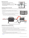
5. Prepare the cable for plug installation:
Using a sharp knife, insert the blade between the cable shield and jacket. Slit the jacket
5
/
8
" back from the
trimmed end of the cable.
Peel the jacket back and remove the slit portion.
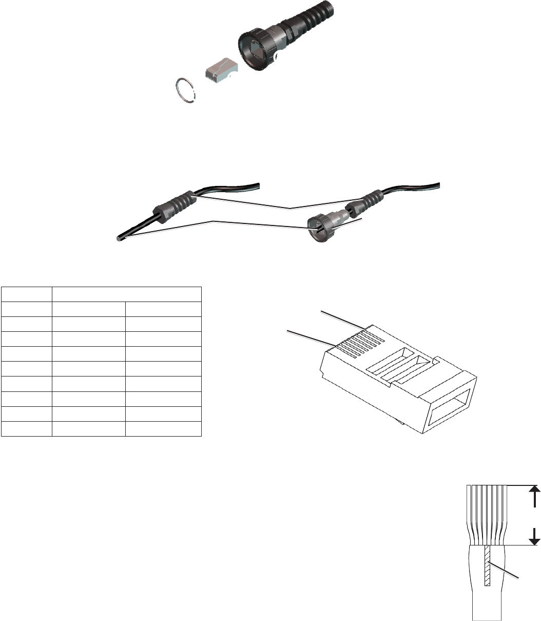
TrimtheshieldandMylarlmawayfromwires.Becarefulnottocutanyofthewires.
Fold the drain wire back over the jacket and trim to approximately
9
/
16
in. (14 mm).
Untwist the wire pairs enough to ensure a proper connection.
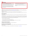
Arrangeindividualwiresinproperorderaccordingtothetableshownabove.Forexample,ifyouhaveidentied
the end of the cable in Step 4 as Side A, arrange the wires for Side A. If you are constructing a custom cable
from bulk wire, you need to make both a Side A and a Side B connection.
Trim the wire ends to an even length, leaving approximately
9
/
16
in. (14 mm) from the ends to the jacket edge.
Place the drain wire on the jacket. Wrap the supplied copper tape around cable as close to the edge of the jacket as possible.
Using a pair of pliers, squeeze the copper tape to pre-form the cable jacket end for easier insertion into the plug. Use caution to avoid
damaging the copper tape.
•
•
•
•
•
•
•
•
•
Position 1
Position 8
Position 1
Position 8
9
/
16
in.
(14 mm)
Drain
wire
9
/
16
in.
(14 mm)
Drain
wire