


4 GMR 600/1200 Series Installation Instructions
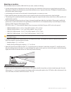
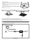
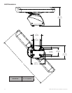
Mounting the Antenna
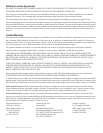
1. Remove the protective cover from the pedestal wave guide.
2. Verify that the antenna wave guide is aligned with the pedestal wave
guide. Slide the antenna onto the pedestal.
3. Securetheantennatothepedestalusingthe8mmhexbolts,at
washers, and spring washers. The 8 mm bolts should be torqued to
70 lbf-in (6 lbf-ft) (.81 kgf-m).
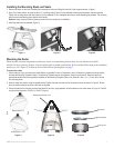
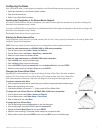
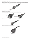
Installing the Voltage Converter Unit
The included voltage converter unit is needed to supply a specic constant voltage to the radar. When installing the voltage converter unit,
consider the following:
The voltage converter requires an input voltage of 10–40 Vdc (20–40 Vdc for the GMR 1204 and GMR 1206).
You must connect the converter to the boat battery through a 15 A slow-blow fuse.
Garmin recommends that you install the voltage converter as close as possible to the selected
power source.
For optimal performance, connect the voltage converter housing to the RF ground of the vessel.
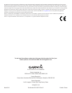
If the input wires need to be extended, follow the recommendations in the wire gauge table.
If the wires are extended, use the supplied heat-shrink butt connectors.
After the connector is crimped, heat the connector to shrink it and provide a water resistant t.
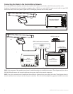
Voltage Converter Unit
+
-
15 A slow-blow fuse
To radar
To RF ground
To power
10–40 Vdc
(20–40 Vdc for
the GMR 1204
and 1206)
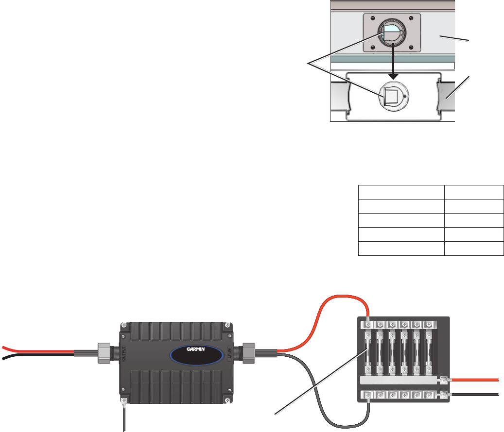
GMR 600/1200 series
Voltage Converter Unit
Sample boat fuse block
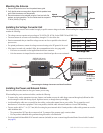
Connecting the Voltage Converter to a Boat Fuse Block
Installing the Power and Network Cables
Route the cable as needed, based on the type of mount you are using.
When installing the power and network cables, consider the following:
To ensure safety, use the appropriate tie-wraps, fasteners, and sealant to secure the cable along a route and through any bulkhead or deck.
Avoid running the cable near moving objects, high-heat sources, or through doorways and bilges.
Avoid installing the cable next to or parallel to other cables, such as radio antenna lines or power cables. This is essential to avoid
interference to or from other equipment. If this is not possible, shield the cable with metal conduit or a form of EMI shielding.
You may need to drill a 1
1
/
4
in. (31.7 mm) hole for routing the power/network cable. Garmin provides a rubber cable grommet to cover the
cable installation hole.
The grommet does NOT provide a waterproof seal. To waterproof the grommet, apply a marine sealant.
You can purchase additional cable grommets through Garmin or a Garmin dealer.
Use the optional eld-installable RJ-45 network connector (included) to create a custom-length Garmin Marine Network cable if needed
(see page 8).
•
•
•
•
•
◦
◦
•
•
•
◦
◦
•
Align the
waveguide faces
Antenna
Pedestal
Align the
waveguide faces
Antenna
Pedestal
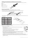
Wire Gauge Table
Distance Gauge
9 ft. 10 in. (3 m) 12 AWG
16 ft. 4 in. (5 m) 10 AWG
21 ft. 3 in. (6.5 m) 9 AWG
26 ft. 2 in. (8 m) 8 AWG
Wire Gauge Table
Distance Gauge
9 ft. 10 in. (3 m) 12 AWG
16 ft. 4 in. (5 m) 10 AWG
21 ft. 3 in. (6.5 m) 9 AWG
26 ft. 2 in. (8 m) 8 AWG