4
3. DISPLAY UNIT
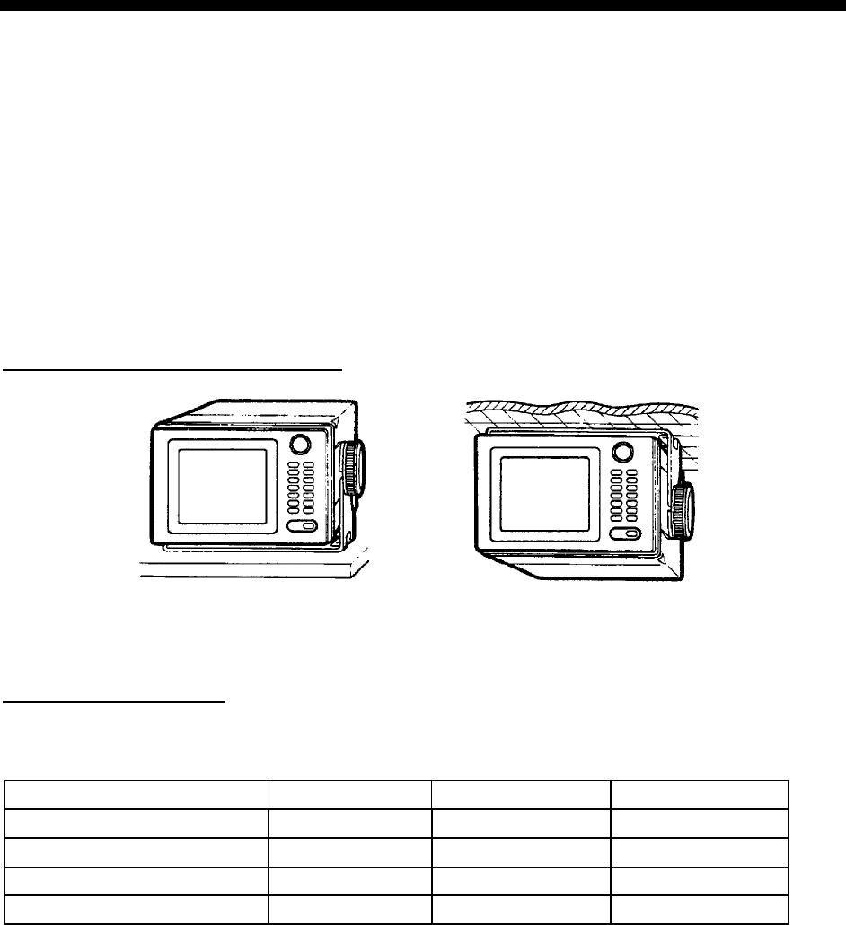
The display unit can be installed with either of four methods as shown below. Refer to the
outline drawing at the end of manual.
• Locate the unit away from exhaust pipes and vents.
• The mounting location should be well ventilated.
• Mount the unit where shock and vibration are minimal.
• Keep the display unit away electromagnetic field generating equipment such as motor,
generator.
• Allow sufficient maintenance space and a sufficient slack in cables for maintenance and
repair.
Table Top and Overhead Mounting
TABLE TOP OVERHEAD
Display unit mounting methods
Flush mounting type F
An optional flush mount kit type F is required. For details, see outline drawing at end of this
manual. (Name: Flush Mount Kit F, Type: OP20-25, Code No.004-393-280)
Name Type Code No. Qty
Self-tapping screw 5X20 000-162-609-10 4
Hex. bolt M6X12 SUS304 000-162-897-10 2
Spring washer M6 SUS304 000-158-855-10 2
Cosmetic panel 20-013-1121 100-234-240 1


