


3. INSTALLATION
25
3.2 Display Unit Installation
Mounting considerations
When choosing a mounting location for the
display unit, keep in mind the following points:
•
Keep the display unit out of direct sunlight.
•
The temperature and humidity should be
moderate and stable.
•
Locate the unit away from exhaust pipes
and vents.
•
The mounting location should be well
ventilated.
•
Mount the unit where shock and vibration
are minimal.
•
Keep the unit away from electromagnetic
field-generating equipment such as motors
and generators.
•
For maintenance and checking purposes,
leave sufficient space at the sides and rear
of the unit and leave slack in cables.
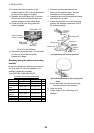
•
Separate the display unit from a magnetic
compass unit by the distances noted below
to prevent interference to the magnetic
compass:
Standard compass: 0.6 m
Steering compass: 0.4 m
•
Be sure the mounting location is strong
enough to support the weight of the unit
under the continued vibration normally
experienced on the boat.
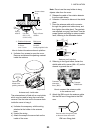
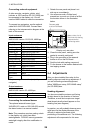
Mounting
The display unit can be mounted on a
desktop or overhead or flush mounted in a
console.
Desktop, overhead mounting
1. Fix the hanger to the mounting location
with four tapping screws (supplied).
2. Fit the knob bolts to the display unit.
3. Set the display unit to the hanger.
4. Tighten the knob bolts securely.
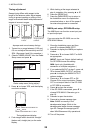
Flush mounting
Cutout a hole in the mounting area, referring
to the outline drawing at the back of this
manual for dimensions. Fasten the display
unit with four screws (M4 x 20, supplied).
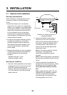
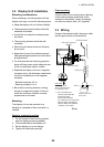
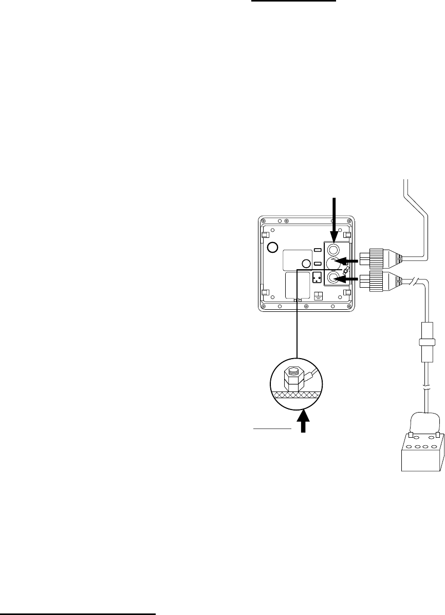
3.3 Wiring
Connect the antenna cable, the power cable
and the ground wire as shown below.
FUSE (5 A)
POWER SUPPLY
12/24 VDC
POWER CABLE
DISPLAY UNIT
ANTENNA UNIT
ANTENNA CABLE*
WHT (+)
BLK (-)
External Equipment
(NMEA)
GROUND
Connect ground
wire to bolt fastened
(or welded) to hull.
* = Do not confuse the
antenna cable with the
transducer cable
for the Echo Sounder
(ex. LS-6100). The transducer
cable is black; the antenna
cable is white and "RADAR"
is written on the cable.
Wiring