


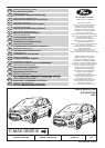

EINBAUANLEITUNG – AUSFAHRBARE
ANHÄNGEVORRICHTUNG
Typ: 307 388
D-Wert: 10,0 kN
Stützlast: 75 kg
Hersteller: Westfalia Automotive GmbH
Am Sandberg 45, D-33378
Rheda-Wiedenbrück
EWG Typgen.-Nr.: e13*94/20*3108
Verwendungsbereich: Ford C-Max 08/2010 ➜
Amtl. Typbezeichnung: DXA
Hinweis:
Der Anbau hat nach dieser Anbauanweisung zu erfolgen.
Eine Anbauabnahme gemäß §19 (3) der StVZO ist nicht
erforderlich. Eine Anbauabnahme hat im Rahmen der
Erteilung der Europäischen Betriebserlaubnis gemäß
94/20/EC Anlage VII 2.1.1 stattgefunden.
Die Betriebserlaubnisdes Fahrzeuges erlischt nicht.
Gemäß § 27 (1) StVZO sind Änderungen der zuständigen
Zulassungsbehörde erst bei deren nächster Befassung mit
den Fahrzeugpapieren unter Einreichung des Fahrzeugbriefs
und Fahrzeugscheins oder der Anhängerverzeichnisse nach
§24 Satz 3 oder des Nachweises nach §18 Abs. 5 sowie der
Unterlagen nach § 19 Abs. 3 oder 4 zu melden.
Achtung: Abweichend davon müssen Änderungen der
zulässigen Achslasten, des Gesamtgewichts, der Nutz-/
Sattel-/ Aufliege- oder Anhängelast unverzüglich gemel-
det werden.
Diese Bescheinigung ist den Fahrzeugpapieren beizulegen,
um sie zuständigen Personen auf Verlangen vorzuzeigen.
Für den Fahrbetrieb sind die Angaben des Fahrzeug-
herstellers bezüglich Anhängelast und Stützlast maßgebend,
wobei die Werte der Anhängevorrichtung nicht überschritten
werden dürfen.
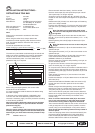
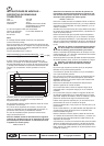
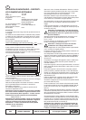
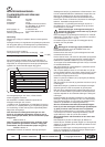
Formel für D-Wert Ermittlung:
Das höchstzulässige Gesamtgewicht der Kombination
Fahrzeug und Anhänger darf nicht überschritten werden. Die
zulässige Gewichtsangabe für das Gespann ist auf dem
Fahrzeug-Typenschild angegeben. Ihr Ford Händler ist Ihnen
gerne behilflich.
Zum Betreiben der Anhängevorrichtung ist der gleichzeitige
Einbau eines Elektrobausatzes erforderlich. Es wird
empfohlen, den Elektrobausatz vor dem Einbau der
Anhängevorrichtung zu installieren.
© Copyright Ford 2010
HM02 E 12346495 000
SKAM5J 19D520 BA
3/43
D
XXXX kg
Anhängelast [kg] x Kfz Gesamtgewicht [kg] 9,81
Anhängelast [kg] + Kfz Gesamtgewicht [kg] 1000
x
= D [kN]
Then check that the release mechanism of the retractable
tow bar is working properly. The way to do this is described
in the motor vehicle manual.
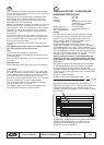
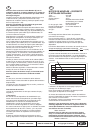
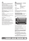
Attach the tow bar's electrical lead to the Bowden cable
with cable ties (2 x O). Fasten the Bowden cable to the
cross member of the tow bar and the motor vehicle with
large cable ties (2 x P) as illustrated.
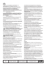
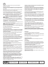
Using the embossing on the back as a guide, cut a 121 mm
diameter circular hole in the carpet of the side panelling.
Then cut approx. 15 mm-long straight slits running radially
outwards from the top and bottom of the hole (using the
embossing as a guide). The slits are to prevent the cover
from twisting.
Insert the front frame of the cover (AM5J-313A16-A*) into
the hole in the carpet from inside. Then fit the rear frame of
the cover (AM5J-313A16-A*) onto the back of the carpet
and snap it into the front frame.
Fit carpet as per workshop manual and insert cap as illu-
strated.
Note: Before inserting the cap the key must be removed
from the hand wheel of the control unit!
Note:
At this point finish installing the electrical kit.
Replace dismantled or loosened parts as described in the
workshop manual.
Reconnect aerial (X3), if fitted, and connect the earth lead to
the battery.
Operating notes:
The coupling ball must be kept clean and well greased (*).
(*) Exception:
When stabilisers are in use which act on the coupling ball,
pro-ceed according to the instructions of the manufacturer
of the stabilisers. When stabilisers are in use, the coupling
ball must be inspected for wear at regular intervals.
As soon as a coupling ball diameter of 49.0 mm or smaller
has been reached at any point, the towing device
must no longer be used in trailer operation; if necessary,
the towing device must be renewed.
The unladen weight of the vehicle will increase by appr.
25 kg following mounting of the towing device.
GB