


© Copyright Ford 2010
HM02 E 12346495 000
SKAM5J 19D520 BA
2/43
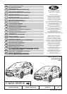
INSTALLATION INSTRUCTIONS –
RETRACTABLE TOW BAR
Type: 307 388
D-value: 10,0 kN
Bearing load: 75 kg
Manufacturer: Westfalia Automotive GmbH
Am Sandberg 45, D-33378
Rheda-Wiedenbrück
EEC type approval no.: e13*94/20*3108
Area of application: Ford C-Max 08/2010 ➜
Off. type designation: DXA
Note:
Fitting is to be executed in accordance with these
instructions.
When using the trailer hitch, always observe the
manufacturer's data regarding trailer load and vertical
load. The figures stated for the trailer hitch must not
be exceeded.
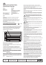
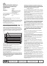
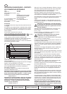
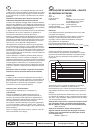
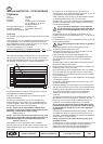
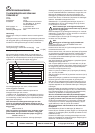
Formula for ascertainment of D-value:
The maximum permissible combined weight of vehicle and
trailer must not be exceeded. The maximum permissible
weight for the car-trailer combination is stated on the
vehicle's identification plate. Your Ford dealer will be
pleased to help you if required.
Before using the coupling device, the correct trailer
electrical kit must be installed.
It is recommended to install the electrical kit before fitting
the trailer coupling.
In the area of the contact surfaces, undersealing, anti-
corrosion wax and noise-deadening material must be
removed. If necessary, apply corrosion protection according
to Ford Service guidelines.
Note: The following delivered equipment must be fitted
with the tow bar (cover kit: your Ford dealer would be
pleased to help you):
AM5J-313A16-A*
Note: For motor vehicles with keyless entry function the
following delivered equipment must also be fitted (aerial
fastening kit: your Ford dealer would be pleased to help
you):
AM3M5J-10K015-A*
GB
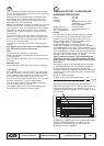
Disconnect earth lead from battery. Jack the vehicle.
Remove rear bumper (X1) and impact strip as per manual.
The impact strip is no longer required.
Screw the nuts of the impact strip (6 x X2) back onto the
threads on the rear wall panel and tighten to the prescribed
torque.
Release aerial (X3), if fitted, from the bumper rail. Fastening
parts are no longer needed.
Push the side members (B + C) of the tow bar into the side
rails and screw up handtight with braces (2 x D) and bolts
(4 x E).
Note: The bolts and screw threads used to bolt
the tow bar to the bodywork must be free from oil
and grease!
Align cross member (A) of the tow bar with the side mem-
bers (B + C) and screw up bolts with washers (4 x F + 4 x G)
handtight.
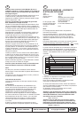
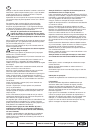
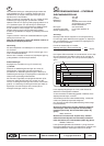
Before tightening the bolts (E) align the braces (2 x D) as
illustrated.
Note: The braces must not rest on the metal plate
flange!
First tighten the screws (4 x E) on the side members to the
specified torque.
Then tighten the screws (4 x F) on the cross member to the
specified torque.
Fasten aerial (X3), if fitted, to the top side of the tow bar's
cross member with the foam part and cable ties
(AM3M5J-10K015-A*) as illustrated.
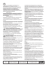
Remove carpet from under the side panelling, rear right, as
per the workshop manual.
On grand motor vehicles, remove blind plug from the floor
panel. The blind plug is no longer required.
On compact motor vehicles, drill a 28.5 mm diameter hole in
the floor panel at the punched point from below. Debur the
hole after drilling and apply corrosion protection as per Ford
guidelines.
Insert dowels for bracket (3 x I) into the holes in the side
wall as illustrated.
Position brackets (K1 or K2) and fasten them to the side wall
with bolts (3x H).
Feed electrical leads and Bowden cable of the tow bar (A)
through the hole in the floor panel as far as the rubber
grommet.
Behind the right-hand side panelling, remove the supply
lead (X4) from the 12 V socket and connect it to the mat-
ching two-pole plug of the tow bar's electrical lead.
Then connect the two-pole jack of the tow bar’s electrical
lead to the 12 V plug socket. Plug the four-pole jack for the
buzzer (small cable cross-section) into the back of the
control unit (L).
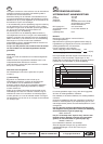
Note: To connect the Bowden cable (A) to the control
unit (L), the silver marking on the hand wheel and the
arrow on the housing must be aligned as illustrated!
Then insert the Bowden cable into the control unit as far as
it will go and push in the clip to lock in position. Push the
control unit (L) onto the bracket (K1 or K2) until it clicks in.
Note: Check that the rubber grommet is firmly seated in
the floor panel!
Insert the clamping shoes of the free electrical lead (A) into
the housing (N) as illustrated and turn the straps down.
Insert the fuse (M) and fasten the fuse holder (N) to the
Bowden cable with the cable tie as illustrated.
XXXX kg
Trailer mass [kg] x gross vehicle mass [kg] 9,81
Trailer mass [kg] + gross vehicle mass [kg] 1000
x
= D [kN]
!
!