1035/El-O-Matic Actuator
Instruction Manual
Form 5417
February 2007
18
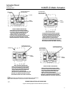
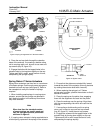
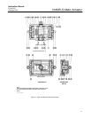
Installing the Bypass Valve
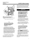
The optional bypass valve should be used when
pressure needs to be stabilized between port A and
port B (see figure 10). The following steps provide
installation of the bypass valve. Removing the
bypass valve simply requires performing these steps
in the reverse order.
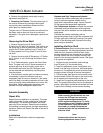
1. Position the O-rings between the bypass block
and the Namur mounting area. Attach the screws
through the bypass block to the Namur mounting
area.
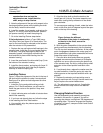
2. Attach the tubing to the fittings.
3. Attach the angle needle valve and the bypass
block to the tubing.
4. Pressure the ports and check for leakage. Check
the pressure to both ports A and B.
Parts Ordering
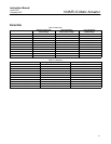
Two types of kits are available. The repair kits
provide O-rings and guide bushing/bearings, and the
O-ring kit provides the O-rings only. Refer to tables 5
and 6 for kit numbers.
WARNING
Use only genuine Fisherr replacement
parts. Components that are not
supplied by Emerson Process
Management should not, under any
circumstances, be used in any Fisher
valve, because they will void your
warranty, might adversely affect the
performance of the valve, and could
give rise to personal injury and
property damage.
Note
Neither Emerson, Emerson Process
Management, nor any of their affiliated
entities assumes responsibility for the
selection, use and maintenance of any
product. Responsibility for the
selection, use, and maintenance of any
product remains with the purchaser
and end-user.
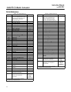
Key numbers and part descriptions are shown in
tables 7 and 8.
Recommended spare parts are marked with an
asterisk (*) following the key number.
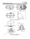
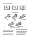
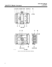
Typical actuator assemblies are shown in figures 11
and 12.
When corresponding with your Emerson Process
Management sales office, please identify the
Actuator as a Type 1035 and provide the actuator
serial number located on the nameplate.


