1035/El-O-Matic Actuator
Instruction Manual
Form 5417
February 2007
16
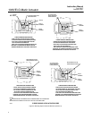
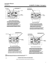
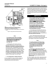
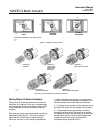
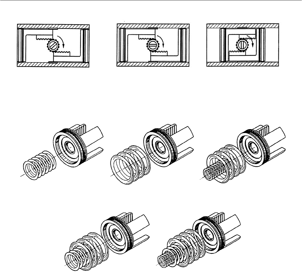
Figure 7. Installing Actuator Pistons
NOTE: PISTONS ARE SHOWN IN THE CODE A POSITION
START
PISTONS AT
BODY ENDS
PISTONS AT
BODY CENTER
45_
0_
90_
75B0509-A
A7042 / IL
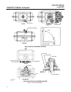
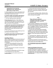
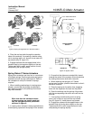
Figure 8. Spring Arrangement for E Series Actuators
SPRING SET 2
MID SPRING
SPRING SET 3
OUTER SPRING
(OR MID +INNER
SPRING AS AN
ALTERNATE)
SPRING SET 4
INNER AND OUTER SPRING
SPRING SET 5
MID AND OUTER SPRING
SPRING SET 6
INNER, MID AND OUTER SPRING
ELO A 4.202
A7040 / IL
Spring Return E Series Actuators
Spring return E Series actuators use from two to a
maximum of six springs. One, two, or three springs
are inserted into each end cap (see figure 8). Refer
to the nameplate to verify the number of springs
required.
Each end cap spring pack incorporates a travel stop
adjustment screw (key 37). This may be used to
adjust the end of the stroke for valve seating in
either the “fail open” or “fail closed” arrangements.
1. When installing used springs in a spring return
actuator, ensure that the springs are replaced in the
identical position from which they were removed.
2. If a spring return actuator is being repaired due to
spring failure, replace all the springs in the actuator.
3. To assemble the spring assembly, install the
spring(s) into the end cap. Be sure that all springs
are seated correctly in the end cap (key 5) and in the
spring holder (key 9). Place the spring holder and
washer on top of the springs, and install the
adjustment screw (keys 34 and 37).


