1035/El-O-Matic Actuator
Instruction Manual
Form 5417
February 2007
14
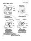
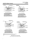
4. Remove the adjustable travel stop/ housing
adjustment (see figure 4).
5. Removing the Pistons: The two pistons (key 2)
can now be removed by rotating the drive shaft,
moving the piston assemblies outward until the
pinion gear has released them.
The gear rack in E Series actuators is machined into
the piston, and so does not have to be removed
separately. If the gear rack is damaged, replace both
pistons.
Removing the Drive Shaft
1. Remove the spring clip (E Series key 35,
P Series key 20) with a pin spanner. Use caution, as
the spring clip is under a great deal of tension. Also,
remove the E Series washers (keys 27 and 21) or
P Series washer and O-ring (keys 21 and 19) from
the shaft.
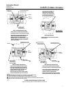
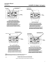
2. Remove the drive shaft (E Series key 3, P Series
key 5, figures 11 and 12) through the bottom of the
actuator.
3. For P Series actuators: remove the Piston Gear
Rack. The gear rack in the P Series actuators is a
separate part (key 6) and is held in place with a
socket head cap screw (key 22). Both gear racks
can be removed and replaced by removing them
from the pistons.
4. Ensure that all actuator parts are clean and ready
for assembly. Inspect the actuator body and
component parts for wear or scratches. If the inside
wall of the body is scored the actuator will leak. Light
traces of scoring, barely detectable to the touch, are
acceptable. Obtain replacement parts from your
Emerson Process Management sales office.
Actuator Assembly
Repair Kits
Repair kits are available for re-assembly. The large
repair kit provides O-rings, guide bands, bushings,
and bearings. The small kit provides a set of soft
parts only for the actuator. Repair kits are available
for standard, low temperature, and high temperature
actuators. Refer to the Repair Kits table at the end of
this manual.
Lubrication
Refer to the Specifications table for temperature
ranges.
Standard and High Temperature Actuator:
Lubricate the actuator moderately with a complex
calcium sulphonate grease suitable for the
application’s temperature range. Use the Parts Kit
for the appropriate temperature application.
Low Temperature Actuator: Lubricate the actuator
moderately with low temperature silicone grease.
Use the Parts Kit for standard and low temperature
applications.
Lubricate the actuator moderately with an
appropriate grease. Apply a light film of grease to all
O-rings, gear racks, bearings, bushings, and guide
bands. In the following steps, lubricate all moving
parts during re-assembly.
Installing the Drive Shaft
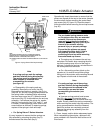
E Series actuators: Some constructions use a Dual
Stop arrangement. The housing adjustment screw is
used with a pin located in the drive shaft, and a
stroking adjustment cam mounted on the shaft for
the stop. Ensure the cam is aligned correctly with
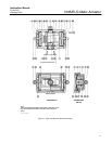
respect to the housing adjustment screw. Use figure
4 as a guide for alignment.
1. Replace the top and bottom shaft bearings
(keys 20 and 12) in the actuator body.
2. Insert the adjustment screw, if applicable, and
thread it into the body a few turns, and hand tighten
the hex nut. The adjustment screw should be loose
enough to allow full travel of the cam and pistons.
3. Place the cam (see figure 4) on the small end of
the drive shaft. Position the cam on the shaft so the
pin is located in the open section of the cam.
4. Install the O-rings and guide bushing on the drive
shaft. The guide bushing may have to be cleaned of
grease, rolled tightly around the drive shaft and held
in place while inserting into the actuator housing.
CAUTION
When inserting the drive shaft, be sure
to keep the O-Rings from becoming
trapped and damaged between the
pinion and the actuator body. To verify
the condition of the O-Rings at the end
of the installation, cycle the actuator 5
times and run a soap bubble test on
the seal on both the top and bottom of
the drive shaft.
Note
Some constructions do not have a
housing adjustment screw. If your


