Spark plugs
Type . . . . . . . . . . . . . . . . . . . . . . . . . . . . . . . . . . . . . . . . . . . . . . . . . . . . Champion RN9YCC or RN9YC
Electrode gap . . . . . . . . . . . . . . . . . . . . . . . . . . . . . . . . . . . . . . . . . . . . . 0.8 mm (0.031 in)
HT leads
903 cc (45) . . . . . . . . . . . . . . . . . . . . . . . . . . . . . . . . . . . . . . . . . . . . . . . Champion LS-07
1116, 1299 and 1301 cc (55, 60 and 70) . . . . . . . . . . . . . . . . . . . . . . . . Champion LS-05
Torque wrench setting Nm lbf ft
Spark plugs . . . . . . . . . . . . . . . . . . . . . . . . . . . . . . . . . . . . . . . . . . . . . . . 25 18
4•2 Ignition system
1 General description
On all models except the 903 ES engine
version, a mechanical contact breaker type
distributor is fitted.
On 45 Super ES models which have the
903 ES engine, an electronic (Digiplex) ignition
system is used which incorporates a
breakerless distributor.
Mechanical contact breaker
system
For the engine to run correctly, it is
necessary for an electrical spark to ignite the
fuel/air mixture in the combustion chamber at
exactly the right moment in relation to engine
speed and load. The ignition system is based
on feeding low tension voltage from the
battery to the coil where it is converted to high
tension voltage. The high tension voltage is
powerful enough to jump the spark plug gap
in the cylinders under high compression
pressures, providing that the system is in
good condition and that all adjustments are
correct.
The ignition system is divided into two
circuits, the low tension (LT) circuit and the
high tension (HT) circuit.
The low tension (sometimes known as the
primary) circuit consists of the battery, the
lead to the ignition switch, the lead from the
ignition switch to the low tension or primary
coil windings, and the lead from the low
tension coil windings to the contact breaker
points and condenser in the distributor.
The high tension circuit consists of the high
tension or secondary coil windings, the heavy
ignition lead from the centre of the coil to the
centre of the distributor cap, the rotor arm,
and the spark plug leads and spark plugs.
The system functions in the following
manner: High tension voltage is generated in
the coil by the interruption of the low tension
circuit. The interruption is effected by the
opening of the contact breaker points in this
low tension circuit. High tension voltage is fed
from the centre of the coil via the carbon
brush in the centre of the distributor cap to
the rotor arm of the distributor.
The rotor arm revolves at half engine speed
inside the distributor cap, and each time it
comes in line with one of the four metal
segments in the cap, which are connected to
the spark plug leads, the opening of the
contact breaker points causes the high
tension voltage to build up, jump the gap from
the rotor arm to the appropriate metal
segment, and so via the spark plug lead to the
spark plug, where it finally jumps the spark
plug gap before going to earth.
The ignition timing is advanced and
retarded automatically, to ensure the spark
occurs at just the right instant for the
particular load at the prevailing engine speed.
The ignition advance is controlled
mechanically, and by vacuum. The
mechanical governor mechanism consists of
two weights, which move out from the
distributor shaft as the engine speed rises,
due to centrifugal force. As they move
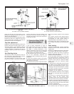
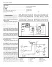
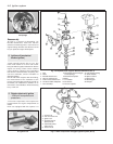
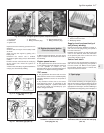
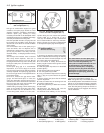
Fig. 4.1 Typical ignition circuit (mechanical contact breaker distributor) (Sec 1)
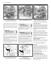
1 Control unit
2 Multi-plug
3 Ignition coil
4 Distributor cap
5 Crankshaft pulley
6 Flywheel
7 Battery
8 Rev counter
9 Spark plugs
10 Wiring connector
S1 Engine speed sensor
S2 TDC sensor
Fig. 4.2 Digiplex electronic ignition system (Sec 1)


