PART D:
BOSCH MONO-JETRONIC
FUEL INJECTION SYSTEM
Warning: Refer to the beginning
of this Section before starting
any work.
Description
1 The Bosch Mono-Jetronic fuel injection
system fitted to the 1372 cc ie engine and
later 999/1108 ‘FIRE’ models is an electroni-
cally-controlled single point injection (SPi)
system. The SPi system is a compromise
between a conventional carburettor fuel
supply system and a multi-point fuel injection
(MPi) system.
2 Compared with a conventional carburettor,
the SPi unit is a relatively simple device. Fuel
is pumped to the SPi unit and then injected
into the inlet system by a single solenoid valve
(fuel injector), mounted centrally on top of the
unit. The injector is energised by an electrical
signal sent from the electronic control unit
(ECU), at which point the injector pintle is
lifted from its seat and atomised fuel is
delivered into the inlet manifold under
pressure. The electrical signals take two forms
of current; a high current to open the injector
and a low current to hold it open for the
duration required. At idle speed the injector
is pulsed at every other intake stroke rather
than with every stroke as during normal
operation.
3 The air-to-fuel mixture ratio is regulated by
values obtained from the ignition coil (engine
speed), engine coolant temperature sensor,
throttle position switch, and the Lambda
sensor in the exhaust system. No adjustments
to the fuel mixture are possible.
4 The throttle position switch enables the
ECU to compute both throttle position and its
rate of change. Extra fuel can then be
provided for acceleration when the throttle is
suddenly opened. Throttle position
information, together with the idle tracking
switch, provide the ECU with the closed
throttle position information.
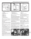
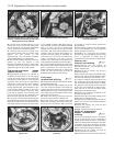
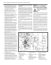
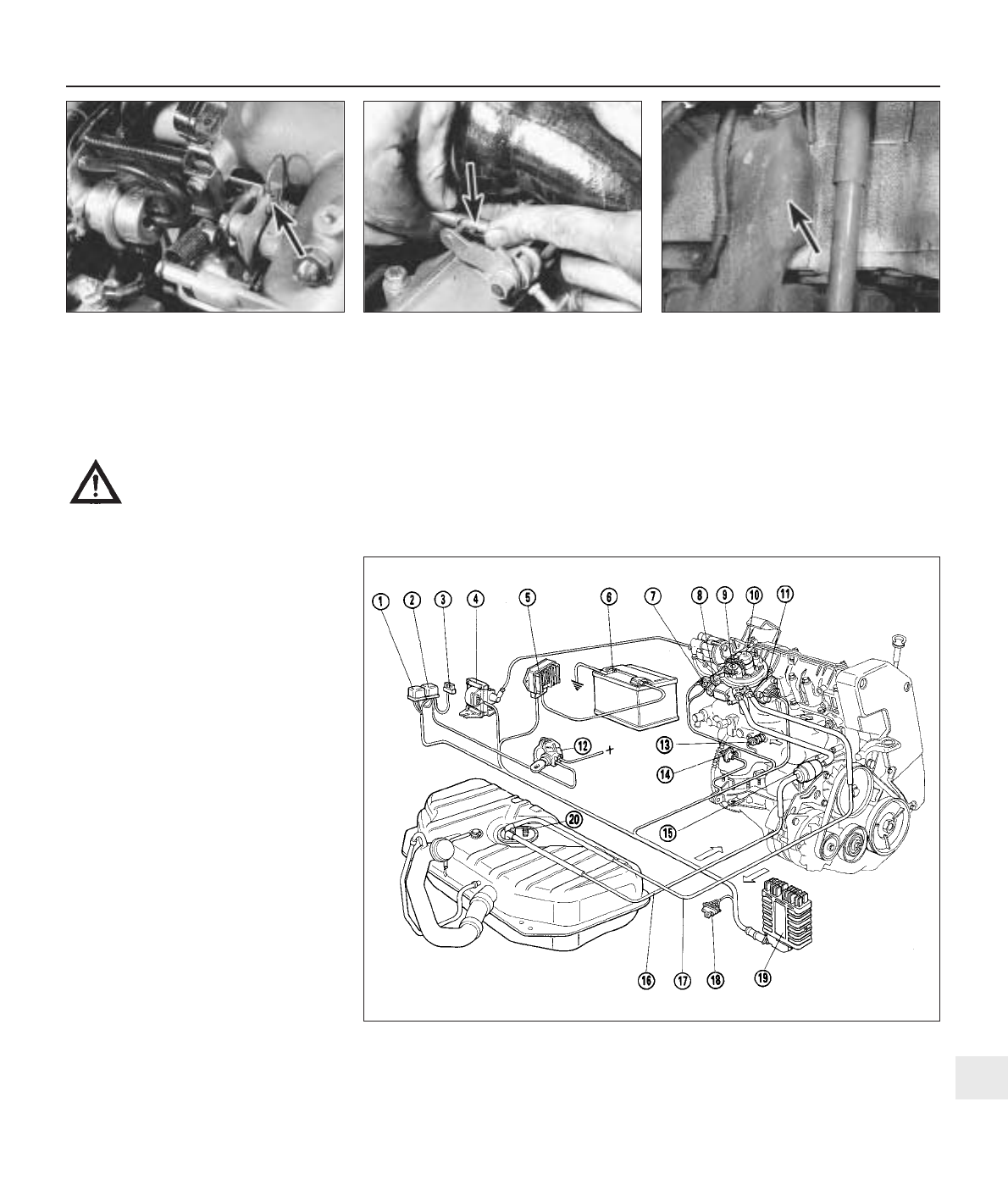
5 The 1372 cc ie system layout and principal
components are shown in Figs. 13.44 and
13.45. Note that the Digiplex 2 electronic
ignition, is not fitted to FIRE models
(999/1108 cc).
6 The fuel system pump is immersed in the
fuel tank and forms a combined unit with the
fuel level sender unit. A cartridge type in-line
fuel filter is fitted to the fuel line, and is located
in the engine compartment.
7 The fuel pressure in the system is
controlled by a mechanical diaphragm
regulator in the injection unit turret. High
pressure in the system causes the diaphragm
to operate and excess fuel is returned to the
fuel tank.
8 The air intake temperature and volume is
regulated to ensure the correct mixture ratio
under all operating conditions. The
temperature of the air passing through the
injection unit is measured by a sensor which
transmits such information to the ECU for the
Supplement: Revisions and information on later models 13•73
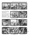
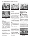
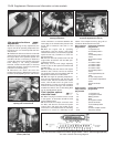
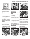
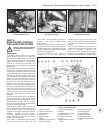
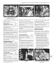
9C.101 Fuel tank anti-blow-back
compartment (arrowed)
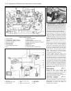
9C.99D Throttle cable balljoint retaining
spring clip (arrowed)
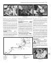
9C.99C Throttle cable nipple (arrowed) in
throttle linkage cut-out
Fig. 13.44 Bosch Mono-Jetronic fuel injection system components and layout on the
1372 cc ie engine (Sec 9D)
1 Fuel pump relay
2 Injection system relay
3 Fuel pump fuse
4 Ignition coil
5 Digiplex 2 ECU
6 Battery
7 Idle speed check actuator
8 Injector connector
9 Fuel pressure regulator
10 Injector
11 Throttle position switch
12 Ignition switch
13 Coolant temperature
sensor
14 Engine speed and TDC
sensor
15 Secondary fuel filter
16 Fuel supply pipe
17 Fuel return pipe
18 Diagnostic socket
19 Fuel injection ECU
20 Fuel pump/level sender
unit
13


