9 Turn the engine clockwise using a suitable
socket on the crankshaft pulley bolt, until the
exhaust valve of No 1 cylinder (valve No 1) is
fully closed; ie the cam lobe is pointing
directly upwards. Alternatively, the engine can
be turned by jacking up one front corner of
the vehicle and supporting it securely on an
axle stand (apply the handbrake and chock
the diagonally-opposite rear wheel before
jacking), engaging top gear and turning the
raised roadwheel in the forward direction of
travel. In both cases, it will be easier to turn
the engine if the spark plugs are removed, but
if this is done, take care not to allow dirt or
other foreign matter to enter the spark plug
holes.
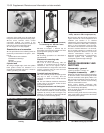
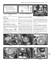
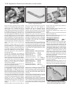
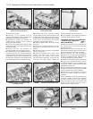
10 Insert a feeler gauge of the correct
thickness between the cam follower shim and
the heel of the No 1 cam lobe (photo). If
necessary, increase or reduce the thickness
of the feeler gauge until it is a firm sliding fit.
Record the thickness of the feeler gauge,
which will represent the valve clearance for
this particular valve.
11 Turn the crankshaft, and repeat the
procedure for the remaining valves, recording
their respective clearances. Note that the
clearance for inlet and exhaust valves differs.
12 If a clearance is incorrect, the relevant
cam follower shim must be removed, and a
thicker or thinner shim must be fitted to
achieve the correct clearance. To remove a
shim proceed as follows.
13 Turn the crankshaft until the relevant cam
lobe is pointing directly upwards.
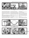
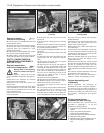
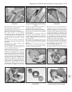
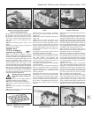
14 The cam follower must now be depressed
in order to extract the shim. FIAT special tool
No 1860642000 is available for this purpose,
but alternatively a suitable tool can be
improvised (photo). The tool should locate on
the rim of the cam follower, leaving enough
room for the shim to be prised out by means
of the cut-outs provided in the cam follower
rim. Depress the cam follower by turning the
crankshaft as described previously until the
relevant cam lobe is pointing directly
downwards, then fit the tool between the
camshaft and the edge of the cam follower to
retain the cam follower in the depressed
position.
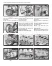
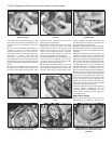
15 Ensure that the tool is securely located, as
there is a risk of personal injury if the tool is
dislodged whilst the cam follower is
depressed, then turn the crankshaft until the
relevant cam lobe is pointing directly
upwards, leaving sufficient room to extract
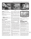
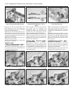
the shim (photo). A pair of angle-nosed pliers
will greatly ease removal of the shim.
16 Once the shim has been extracted,
establish its thickness. The thickness in mm
should be stamped into the face of the shim,
although it is possible for wear to obliterate
the number, in which case the use of a metric
micrometer is the only way to accurately
establish the thickness.
17 Refer to the clearance recorded for the
valve concerned. If the clearance recorded
was larger than that specified, a thicker shim
must be fitted, and if the clearance recorded
was smaller than that specified, a thinner shim
must be fitted. The required thickness of shim
can be
calculated as follows.
Sample calculation - clearance too large:
Desired clearance (A) 0.40 mm
Measured clearance (B) 0.45 mm
Difference (B - A) + 0.05 mm
Original shim thickness 3.40 mm
Required shim thickness 3.40 + 0.05 =
3.45 mm
Sample calculation - clearance too small:
Desired clearance (A) 0.50 mm
Measured clearance (B) 0.35 mm
Difference (B - A) 0.15 mm
Original shim thickness 4.55 mm
Required shim thickness 4.55 - 0.15 =
4.40 mm
18 Shims are available in thicknesses from
3.20 to 4.70 mm, in steps of 0.05 mm. Note
that if several shims have to be changed, they
can often be interchanged, thus avoiding the
need by buy more new shims than are
necessary.
19 The shims should be fitted to the cam
followers with the stamped thickness marking
against the face of the cam follower.
20 After fitting a shim, rotate the crankshaft
as described previously until the relevant cam
lobe is pointing directly downwards (resting
on the shim), then carefully remove the tool
used to retain the follower in the depressed
position.
21 Re-check each relevant valve clearance
after fitting the shim.
22 On completion, where applicable, lower
the vehicle to the ground.
23 Refit the camshaft cover, using a new
gasket.
24 On the ie engine, reconnect the hoses and
refit the air cleaner unit.
25 On the Turbo ie engine, reconnect the air
hose and the accelerator cable.
Timing belt tensioner
and sprockets -
removal and refitting #
Note: The timing belt must be renewed after
removal: never refit a used drivebelt. When
fitting the new timing belt it will need to be
correctly tensioned and to achieve this the
manufacturers specify the use of special tools
1860745200 (18760745300 on Turbo model)
and 1860745100. If these tools are not readily
available, an approximate setting can be
made, but in this instance it is strongly
recommended that the car be taken to a FIAT
dealer at the earliest opportunity to have the
belt tension checked and correctly set using
the recommended tools.
26 Loosen off the front right-hand side wheel
bolts, then raise and support the car at the
front end on axle stands. Remove the front
right-hand roadwheel.
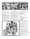
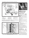
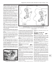
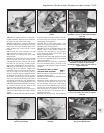
27 Remove the underwing shield from the
right-hand wheel arch to allow access to the
lower timing cover and alternator fixings (photo).
13•38 Supplement: Revisions and information on later models
7B.27 Underwing shield (A) showing
central compression pin (B) and retaining
clip (C). Drive pin through clip to remove
7B.15 Removing a shim from a cam
follower
7B.14 Special tool for retaining cam
follower in depressed position
7B.10 Measuring a valve clearance
(No 2 valve shown)


