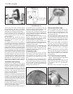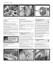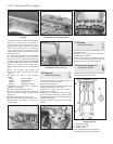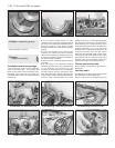
head gasket must be fitted (ALTO visible) so
that the oil pressure hole in the block is
central in the copper ringed cut-out in the
gasket (photos). Make sure that the gasket
surfaces on head and block are perfectly
clean and free from oil, otherwise the heat
sealing (polymerisation) process of the gasket
cannot take place.
22 Tighten the cylinder head nuts and bolts
to the specified torque, in the sequence
shown in Fig. 1.30. Follow the procedure very
carefully owing to the special type (ASTADUR)
of gasket used which hardens in use. Always
keep a new cylinder head gasket in its
nylon cover until just before it is required for
use.
23 Oil the cylinder head bolts and
washers and allow them to drain for thirty
minutes.
24 Tighten the bolts in the following
stages:
Stage 1 20 Nm (15 lbf ft)
Stage 2 40 Nm (30 lbf ft)
Stage 3 Through 90º
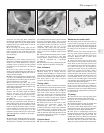
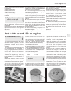
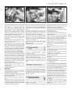
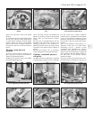
Stage 4 Through 90º (photo)
Retightening the bolts after a running-in
mileage is not required.
25 Fit the timing belt (Section 28).
26 Check the valve clearances (Section 26)
after the camshaft carrier has been fitted
(Section 27).
27 Bolt on the camshaft carrier cover.
28 Reconnect all hoses, leads and controls.
29 Reconnect the battery and refill the
cooling system.
30 Sump pan -
removal and refitting
1
1 Position the car over an inspection pit or
raise the front wheels on ramps.
2 Disconnect the battery.
3 Drain the engine oil. Unbolt and remove the
flywheel housing lower cover plate.
4 Unbolt the sump pan and remove it
together with its gasket.
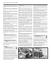
5 Refitting is a reversal of removal. Always
use a new gasket locating it on clean mating
flanges and tighten the fixing bolts evenly and
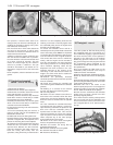
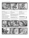
progressively (photo).
6 Fill the engine with oil and reconnect the
battery.
31 Oil pump -
removal and refitting
1
1 Remove the sump pan as described in the
preceding Section.
2 Unbolt the oil pump and withdraw it
complete with driveshaft.
3 Use a new gasket when refitting the pump
and prime the pump by pouring engine oil
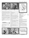
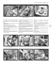
through the pick-up filter screen (photo).
32 Pistons/connecting rod -
removal and refitting
3
1 Remove the sump pan and the oil pump as
described in Sections 30 and 31.
1•26 1116 cc and 1301 cc engine
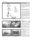
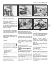
Fig. 1.31 Piston/connecting rod assembly
diagram (Sec 32)
1 Matching numbers
2 Gudgeon pin offset
3 Auxiliary shaft
Arrow indicates direction of rotation of
crankshaft viewed from timing belt end
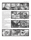
29.24 Tightening a cylinder head bolt
through 90º using a protractor
31.3 Bolting on the oil pump30.5 Locating the sump pan gasket
29.21C Lowering cylinder onto block29.21B Cylinder head gasket in position -
cylinder block drain plug arrowed
29.21A Cylinder head gasket top face
marking


