7 Carburettor idle speed and
mixture - adjustment
4
1 All carburettors have their mixture
adjustment set in production. The screw is
fitted with a tamperproof cap.
2 Under normal circumstances, only the idle
speed screw need be adjusted to set the
engine idle speed to the specified level.
3 Before attempting to adjust the idle speed
or mixture, it is important to have the ignition
and valve clearances correctly set and the
engine at normal operating temperature with
the air cleaner fitted.
4 Where the mixture must be adjusted, prise
out the tamperproof plug and turn the mixture
screw in to weaken or out to enrich the
mixture until the engine runs smoothly without
any tendency to “hunt”.
5 Ideally an exhaust gas analyser should be
used to make sure that the CO level is within
the specified range.
6 Once the mixture has been correctly set,
re-adjust the idle speed screw.
8 Carburettor -
removal and refitting
2
1 Remove the air cleaner.
2 Disconnect the flow and return fuel hoses
from the carburettor and plug them.
3 Disconnect the coolant hoses from the
carburettor throttle valve plate block.
Provided the cooling system is cold and not
under pressure there should be almost no loss
of coolant. Tie the hoses up as high as
possible with a piece of wire.
4 Disconnect the vacuum and vent hoses
from the carburettor.
5 Disconnect the throttle and choke controls
from the carburettor.
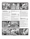
6 Unscrew the mounting flange nuts and lift
the carburettor from the intake manifold
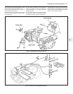
(photo).
7 Refitting is a reversal of removal. Use a new
flange gasket and make sure that the fuel
return hose is routed above the air cleaner
intake.
9 Carburettor
(Weber 32 ICEV 50/250/1) -
servicing and adjustment
4
1 The carburettor top cover with float may be
removed without the need to withdraw the
carburettor from the manifold. The other
adjustments described will require removal of
the carburettor.
2 Unscrew the filter plug from the top cover,
clean the filter screen and refit it.
3 Extract the top cover fixing screws, lift the
cover and tilt it to unhook it from the
diaphragm capsule link rod.
4 Access to the fuel inlet needle valve is
obtained by carefully tapping out the float arm
pivot pin. Take care, the pivot pin pillars are
very brittle.
5 Check that the needle valve body is tight
otherwise fuel can bypass the needle valve
and cause flooding.
Float adjustment
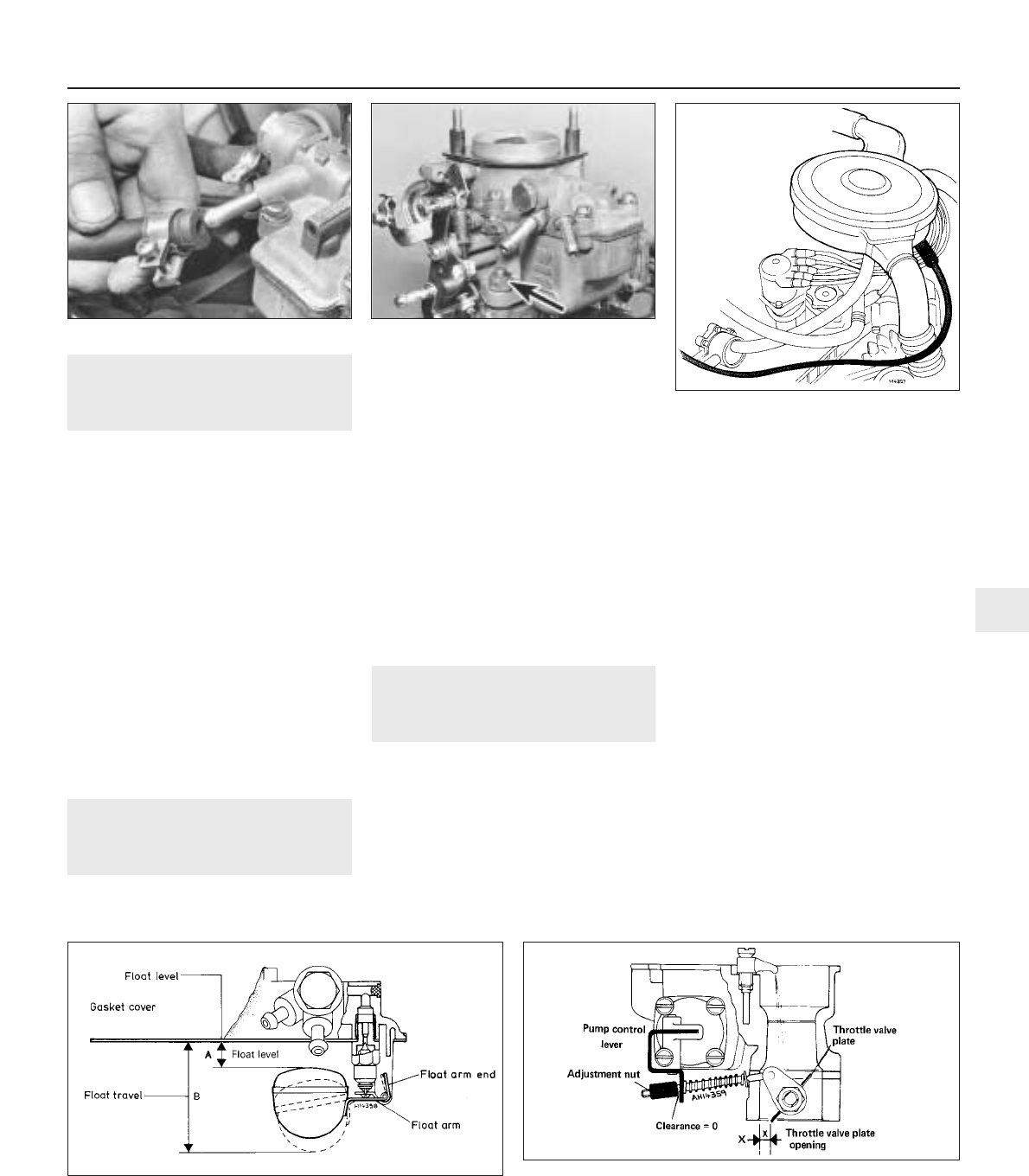
6 Reassemble and check the float setting. Do
this by holding the top cover vertically so that
the float hangs down under its own weight.
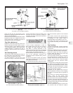
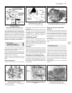
Measure dimension (A) (Fig. 3.10) which
should be between 1 0.50 and 11.10 mm
(0.41 to 0.44 in) with the gasket in position. If
necessary, bend the float arm tab to adjust.
7 Now check the float travel which should be
45.0 mm (1.77 in). If adjustment is required,
bend the end of the float arm.
Accelerator pump stroke
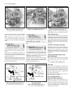
8 Using a twist drill as a gauge, open the
throttle valve plate through 3.5 mm (0.138 in).
9 Turn the nut on the accelerator pump rod
until it just makes contact with the pump
control lever.
Fast idle adjustment
10 With the choke valve plate fully closed by
means of the control lever, the throttle valve
Fuel system 3•7
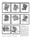
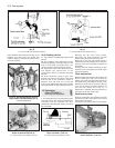
Fig. 3.9 Fuel return hose correctly located
(Sec 8)
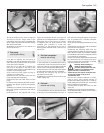
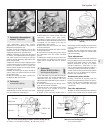
8.6 Carburettor mounting flange nut8.2 Fuel hose at carburettor
Fig. 3.10 Float setting diagram (Weber 32 ICEV 50/250) (Sec 9)
A = 10.5 to 11.0 mm (0.41 to 0.44 in) B = 45.0 mm (1.77 in)
Fig. 3.11 Accelerator pump setting diagram
(Weber 32 ICEV 50/250) (Sec 9)
X = 3.5 mm (0.138 in)
3


