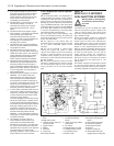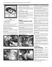
6 On 999, 1108 and 1372 cc engines, the
distributor is driven from the rear end of the
camshaft.
7 On the 1116 and 1299/1301 cc engines, the
distributor is driven from an extension of the
oil pump driveshaft which is geared to the
auxiliary shaft.
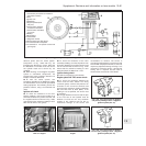
8 The distributor contains a reluctor mounted
on its shaft, and a magnet and stator fixed to
the baseplate.
9 Ignition advance is controlled in the
conventional way mechanically by centrifugal
weights and a diaphragm unit for vacuum
advance.
10 Instead of the conventional method of
interrupting the low tension circuit to generate
high tension voltage in the coil by means of a
mechanical contact breaker, when the
electronic ignition is switched on, the
switching of the transistors in the electronic
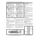
control unit (ECU) prevents current flow in the
coil primary windings.
11 Once the crankshaft rotates, the reluctor
moves through the magnetic field created by
the stator and when the reluctor teeth are in
alignment with the stator projections a small
AC voltage is created. The ECU amplifies this
voltage and applies it to switch the transistors
and so provide an earth path for the primary
circuit.
12 As the reluctor teeth move out of
alignment with the stator projections the AC
voltage changes, the transistors in the ECU
are switched again to interrupt the primary
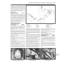
circuit earth path. This causes a high voltage
to be induced in the secondary winding.
Distributor
(breakerless type) -
removal and refitting #
13 Removal of the distributor on the 903,
1116, 1299 and 1301 cc engines is as
described in Chapter 4, Section 6.
14 On 999, 1108 and 1372 cc engines, mark
the position of the distributor clamp plate in
relation to the cylinder head surface.
15 Unclip the distributor cap and move it to
one side with the HT leads attached.
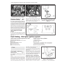
16 Disconnect the LT lead plug and, where
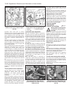
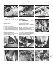
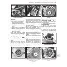
applicable, the vacuum hose (photo).
17 Unscrew the distributor fixing nuts and
withdraw the unit.
18 The distributor drive is by means of an
offset dog no special procedure is required to
refit it. Providing the dog engages in its slot
and the distributor body is turned to align the
marks made before removal, the timing will
automatically be correct.
19 If a new distributor is being fitted (body
unmarked), set No. 4 piston at TDC (0º) by
turning the crankshaft pulley bolt until the
timing marks on the crankshaft pulley and
engine front cover are in alignment.
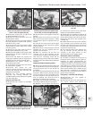
20 Align the drive dog and fit the distributor
then turn the distributor body until the contact
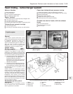
end of the rotor is aligned with the arrow on
the distributor dust shield.
21 Tighten the distributor clamp nuts. Refit the
cap and disconnected components and then
check ignition timing using a stroboscope.
Distributor (breakerless
type) - overhaul #
22 It is recommended that a worn out or
faulty distributor is renewed. However,
individual components such as the cap, rotor,
reluctor, magnet/stator/baseplate assembly,
vacuum diaphragm unit, and drive gear or dog
are available separately.
Breakerless
ignition system
components - testing ™
23 A voltmeter and an ohmmeter will be
required for this work.
Primary circuit voltage
24 Turn on the ignition, and using a voltmeter
check the voltage at the ignition coil LT
terminals. Any deviation from battery voltage
will indicate a faulty connection, or if these are
satisfactory, then the coil is unserviceable.
Magnetic impulse generator winding
25 Remove the distributor and ECU and
disconnect their connecting leads.
26 Connect an ohmmeter to the impulse
generator terminals and note the reading. The
resistance should be as given in the Specifi-
cations at the beginning of this Chapter.
27 Now check between one of the impulse
generator terminals and the metal body of the
distributor. Infinity should be indicated on the
ohmmeter. If it is not, renew the impulse
generator carrier plate. Note: When carrying out
this test it is imperative that the connections are
remade as originally observed. Also ensure that
there is no possibility of the ECU supply (red)
cable and earth cable making contact in service.
Ignition coil winding resistance
28 Check the resistance using an ohmmeter
between the coil LT terminals. Refer to the
Specifications for the expected coil resistance.
29 Check the resistance between the LT lead
socket on the coil and each of the LT
terminals. Refer to the Specifications for the
expected coil resistance.
30 The rotor arm resistance should be
approximately 5000 ohms.
Microplex ignition system -
description
31 This system is fitted to the 1301 and
1372 cc Turbo ie models, and comprises the
following components.
Electro-magnetic sensors
32 Two sensors are used to pick up engine
speed and TDC position directly from the
crankshaft.
Pressure and vacuum sensor
33 This converts inlet manifold vacuum
pressure into an electrical signal for use by
the electronic control unit (ECU).
Anti-knock sensor
34 This converts “pinking” detonations which
occur within the combustion chambers into
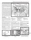
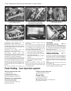
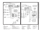
an electrical signal for use by the ECU (photo).
Electronic Control Unit (ECU)
35 This computes the optimum ignition
advance angle from the sensor signals
received, and controls the action of the
ignition unit (photo).
13•86 Supplement: Revisions and information on later models
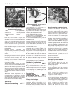
Fig. 13.72 Rotor aligned with arrow on
distributor dust shield - 999 and 1108 cc
engines (Sec 10)
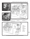
1 ECU
2 Ignition coil
3 Distributor
4 Vacuum advance
unit
5 Pick-up filter with
calibrated opening
for atmospheric
pressure
Fig. 13.71 Location of electronic ignition
components on early models with
breakerless ignition (Sec 10)
10.16 Distributor LT lead connecting plug


