


Installation:
CAUTION: Disconnect the battery during
installation.
Tighten nuts on the
backclamp only slightly more than you
can tighten with your fingers. Six inch-
pounds of
torque are sufficient. Over-
tightening could result in damage to the
instrument and may void your warranty.
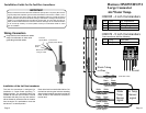
1. Cut a 3-3/8” diameter hole in the dash
and mount the gauge with the backclamp
supplied.
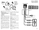
Follow the enclosed instructions for
installing the sender. Once the sender is
installed and you have run the cables to
the Commander, connect the wires from
the sender to the corresponding Small or
Large connectors as illustrated using the
butt connectors supplied. The butt
connectors have a heat activated
waterproofing. Once the butt connections
have been crimped slowly apply heat with
a heat gun until you see sealant coming
out of
the connector ends. It is
recommended to wrap the connections
together with electrical tape for further
protection.
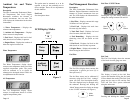
2. Small Connector Socket
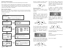
Tachometer with Fuel Flow
Follow the wiring diagram at the end of
this manual for wiring connections.
HN0356.
SystemCheck® connections can be found
on HN0358.
Tachometer with Ambient Air and
Wa
ter Temperature.
Follow the wiring diagram at the end of
this manual for wiring connections.
HN0355.
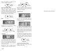
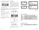
3. Large Connector Socket
Tachometer
with Fuel Flow
Follow the wiring diagram at the end of
this manual for wiring connections.
HN0354.
SystemCheck® connections can be found
on HN0358.
Ta
chometer with Ambient Air and
Water Temperature.
Follow the wiring diagram at the end of
this manual for wiring connections.
HN0355 or HN0372 for 5 inch
Commanders..
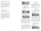
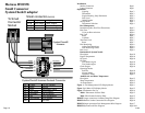
Used for all splices.
Wire
s
Heat Shrink Tu
be
(red or b
lue)
Metal Butt Connecto
r
(red or blue).
Used for all splices.
Larger
Connecto
r
Socket
Smalle
r
Connecto
r
Socket
Smal
l
Plug
Large
Plug
Note: For wiring
diagram for the
Large Connector
Plug see HN0354
SystemCheck HN0358
or HN0355 for
Te
mperature senders.
HN0372 for 5 inch
Commanders.
Note: For wiring
diagram for the
Small Connector
Plug see HN0356
SystemCheck HN0358
or HN0355 for Temperature senders.
Page 1
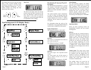
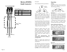
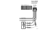
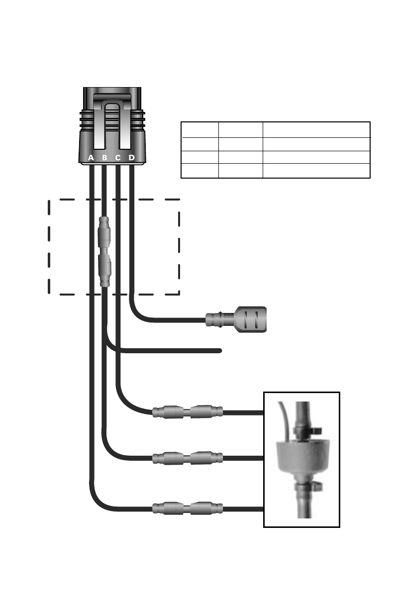
Harness HN0354
Large Connector
Large Plug(CN0082)
To Commander
Shrink Tubing
or Wrap
Green
Pin A Red Fuel Flow Power
Pin B Green Sender Grounds
Pin C White Fuel Flow Signal
Pin D Pink Fuel
Tank Level
ECR 1903 12/21/01
(Tank Sender Ground)
(Sender Ground)
(Sender Power)
(Sender Signal)
Fuel Flow Transducer
Pink
(Fuel Level)
White White
Red Black
Green Shield
Page 17
This manual for 4 or 5 inch Commanders
with
1) Tach/Hour/Fuel Flow.
2) Tach/Hour/SystemCheck®/Fuel Flow.
3) Tach/Hour/Ambient Air/Water
Temperature.