


Ambient Air and Water
Temperature
Description
Th
e Faria Commander Tachometer/ Water-
Air Temperature/ Fuel Level/ Engine
Hourmeter combines the features of
several instruments into one unit. The
LCD displays the information for the other
instruments:
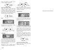
1) Water Temperature - Displays the
current water temperature.
2) Ambient Air Temperature - Displays
shows current air temperature
3) Fuel Level - Displays fuel level in fuel
tank (based on level sender) in percent.
4) Engine Hours - Displays the number of
hours the engine has been run.
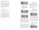
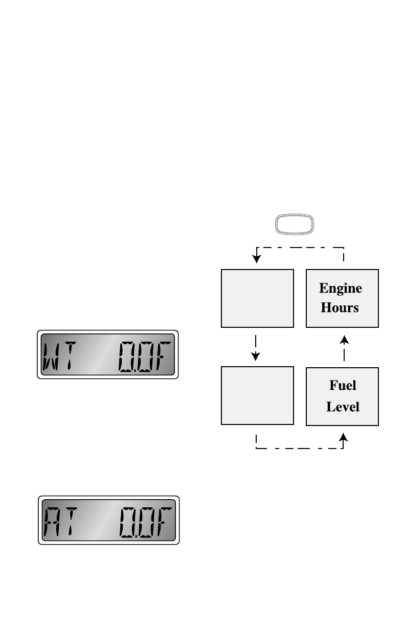
Wa
ter Temperature
The
Water Temperature display shows
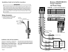
current water temperature based on a Faria
supplied temperature probe. The probe
must be mounted so as to always be
submerged to the depth desired. There are
no adjustments for this function.
Air Temperature
The Air Temperature display shows
current air temperature based on a Faria
supplied temperature probe.
Th
e probe must be mounted so as to be
ex
posed to free air but preferably not in
direct sunlight. There are no adjustments
for this function.
Fu
el Level
See description above.
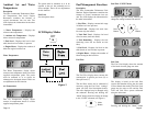
M
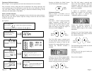
LCD Display Modes
Figure 2
Quick
Press
Water
Temp.
Ambient
Air Temp.
Page 12
Fuel Management Functions
Description
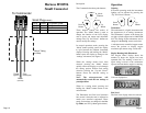
The Faria Commander Tachometer/ Fuel
Monitor/ Engine Hourmeter combines the
features of several instruments into one
unit. The LCD displays the information for
th
e other instruments:
1) Fuel Flow - Displays current fuel usage
in
Gallons or Liters per hour.
2) Fuel Used - Displays fuel used since
la
st reset (trip fuel meter).
3) Total Fuel Used - Displays fuel used
si
nce last reset (total fuel meter).
4) Fuel Rem
aining - Displays the fuel
remaining s
ince last set (based on fuel
flow).
5) Fuel Level - Displays fuel level in fuel
tank (based on level sender) in percent.
6) Engine Hours - Displays the number of
hours the engine has been run.
Fu
el Flow
Th
e Fuel Flow display shows current fuel
consumption in gallons per hour (G) or
liters per hour (L).
Th
e fuel flow sensor can be calibrated if
necessary using the Fuel Used “settings”
menu (see Fuel Used description below).
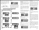
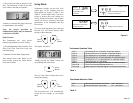
Th
e units displayed may be changed using
the
submenu. Pressing and holding the
“Mode” button causes the display to change
to the “UNITS” submenu (see Figure 1).
Fu
el Flow “UNITS” Menu
Pressing the “Up” and “Down” buttons will
ch
ange the setting between GH and LH.
Fu
el Used
Th
e Fuel Used display shows the amount
of fuel used since the gauge was reset.
The display is
based on the fuel flow
sys
tem and therefore filling the fuel tank
will not disturb the reading. The Fuel Used
gaug
e may be reset to zero and the Fuel
Used and Fuel Flow system calibrated
using the sub menus.
Pressing and holding the “Mode”
button
M
Mode
Button
Down
Button
Up
Button
Page 6