


Tachometer Full Scale Selection
Refer to Figure 3 for an explanation of each of the tachometer full scale selections.
This i
s normally a factory setting that needs no adjustment. The setting adjusts the “full
scale” operating range of the tachometer to match the dial on the instrument. Using the
“Up” and “Down” buttons, adjust the setting to match the maximum reading on the
tachometer dial, 4000, 6000, or 7000 RPM.
Fu
el Level Sender Selection
Refer to Figure 3 and Table 2 for an explanation of each of the fuel level sender selections.
Using the “Up” and “Down” buttons, adjust the setting to match the fuel level sender
installed in the fuel tank.
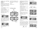
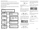
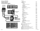
Set-Up Mode
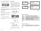
Flashes
then shows current Tac
h
selection.
Flashes
then shows current
number of teeth (pulses)
per rev. if
was selected.
Flashes
and then shows
current
RPM if
Screen shows:
Number of teeth (pulses) per rev
adjusts teeth (pulses) per rev
Screen shows:
Measured RPM
adjusts Pointer RPM shown to
match displayed calibration
reference
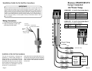
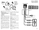
Enter Setup Mode:
Press both the buttons while turning on instrument
.
To exit the setup mode, press and hold the button.
Set-Up start screen ,
shows that setup mod
e
has been entered
.
M
Screen shows:
Screen shows:
Default = TAC3
was selected.
Page 14
.
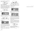
Pressing and holding the “Mode” button
sets the instrument to normal operation.
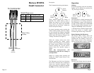
Tachometer Selectio
n
Refer to Figure 3 and Table 1 for an
explanation of
each of the tachometer
selections.
T SCAL
E-
The “TAC 1” - “TAC 7” settings are normal
engine tachometer settings based on
dif
ferent engine options found on most
boats. Using “Up” and “Down” buttons,
adjust the setting to match the engine in
the boat as shown in Figure 3.
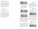
Th
e “TAC 8TH” setting is normally used
on diesel engines with a magnetic pick-up
mea
suring the number of teeth on the
flywheel of the engine. When this option is
selected, the “TEETH” submenu is
av
ailable.
Usin
g the “Up” and “Down” buttons, adjust
th
e number shown in the “TEETH” display
until the number matches the published
number of flywheel teeth for the engine.
Th
e “TAC 9VA” setting is normally used
wh
en a belt driven alternator supplies the
tachometer signal OR when no other
method of selecting the tachometer mode
gives correct readings.
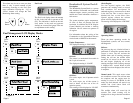
A digital or mechanical refe
rence
tachometer is needed to use this
option.
When this option is selected, the
“VARIABL” submenu is available.
Connect the reference tachometer as
required. Operate the engine at a
convenient RPM as high as can be safely
maintained.
Usin
g the “Up” and “Down” buttons, adjust
the number shown in the display to match
the reference tachometer.
Th
e tachometer pointer should also match
th
e reference tachometer.
SENDER
Allows y
ou to set the type of sender you
are using. See Figure 3.
Set up is now complete.
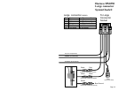
M
Mode
Button
Down
Button
Up
Button
Down
Button
Up
Button
Down
Button
Up
Button
Page 4